
5 Insulation Techniques
Deepwater fields are economically developed using subsea completions, with hydrocarbon fluids typically conveyed via multiphase pipelines and flowlines to an existing floating production platform. These flowlines operate in a low ambient temperature, high external pressure environment, conducive to the formation of paraffin deposits or hydrates. The leading strategy to circumvent these deleterious effects is to minimise heat loss from the system using insulation. The proper design of flowline insulation requires a balance among the high cost of the insulation, the intended operability of the system, and the acceptable risk level.
Economical long distance production of multiphase wellstream fluids (oil, gas condensate, and water) can be achieved with an effectively insulated flowline by minimising the costs, revenue loss, and risks from the following:
Hydrate formation during steady state or transient flowing conditions
Paraffin deposit on the inner pipe wall, that can result in flowline obstruction or flow rate reductions
Adverse fluid viscosity effects at low temperatures which lead to reduced hydraulic performance or difficulties restarting a cooled system after a short shut-in
Additional topside facilities required to heat produced fluids to aid separation processes.
The overall heat transfer coefficient (U or U-value) is the parameter normally used to quantify the heat retention characteristics of an insulated flowline. The U-value is directly proportional to the heat transfer radially from the flowline centreline. The U-value can be calculated from the flow behaviour of the production fluid, the thermal properties and geometry of the insulation system, and the ambient environmental conditions.
Thermal insulation systems for subsea pipelines are normally designed for an overall heat transfer coefficient U-value (W/m²°C) that aims at preventing a temperature drop below the wax and hydrate formation limits for most of the expected steady state flow regimes. However, transient conditions that frequently may occur at temporary stops or long lasting shut downs, can also predict a U-value giving the operator time to respond before the fluid supercooling reaches critical limits.
![[Tip]](tip.png) | Tip Click these links below for access to 3D resources: |
5.1 Wet Insulation Pipe System
5.1.1 General
Wet insulation systems are flowlines or pipelines that have insulation coatings applied directly to the pipe or corrosion coating. The insulation is not protected by a steel jacket pipe as with either pipe-in-pipe or bundled systems. The essence of a non-jacketed insulation is that it must be able to withstand the hydrostatic pressure of the subsea environment, the crushing loads during installation and retain its insulation properties in wet environment for the predicted field life.
Wet insulation and corrosion protection systems have been used in the North Sea for more than 15 years and were initially based on the use of bitumen and polyethylene elastomers. Good experience has later encouraged the supplier industry to develop numerous options of solid and foamed polymers/elastomers material that can be tailor-made for most applications and demands in shallow water.
For the growing activities in deeper waters (>300m) the options are, however, reduced to the use of solid materials, special engineered polymer composites and epoxy syntactic with hollow glass or silicate microspheres, that can sustain a water depth of more than 1000m and a temperature of 135°C.
The pipeline wet coating is then composed either of external anti-corrosion coating or combination of anti-corrosion and insulation coatings.
5.1.2 Anti-Corrosion
Anti-corrosion coatings are covered by DNVGL recommended practice RP-F106.
Common systems used include:
Fusion bonded epoxy (FBE);
Thermoplastics - polypropylene and polyethylene;
Elastomers – polychloroprene.
The features of FBE are:
Applied as a powder sprayed onto hot rotating pipe at 250°C;
Thin coating - typically 0.5mm;
Excellent corrosion resistance but, as a thin coating, not very tough;
Temperature limit - about 100°C dry and 70°C wet;
Can be used beneath concrete but requires addition of adhesive bands.
Thermoplastics:
The thermoplastics in general use as anticorrosion coatings are polyethylene (PE) or polypropylene (PP).
Polychloroprene
Polychloroprene is used in harsh environment applications such as risers in the splash zone and not as a general pipeline coating. The features are:
Sheet polychloroprene bonded to pipe;
Autoclaved to cure;
Typically used in harsh environments e.g. splash zone;
Thick coating typically 6-12mm;
Temperature limit is about 100°C;
Anti-fouling materials can be bonded to the outside of the coating.
5.1.3 Thermal Insulation
The primary insulation materials used are polymeric coatings. There are various options for thermal insulation coatings although generally they fall into three categories:
Solid coatings;
Syntactic coatings;
Foam coatings.
Solid coatings in polyurethane (PU) or polypropylene (PP) are of low relative thermal efficiency compared to the syntactic or foamed coatings so are generally used either as field joint coatings, water or thermal barrier layers in multi-layer foam systems.
Syntactic coatings consist of microspheres within a polyurethane or polypropylene matrix. The microspheres are either plastic or, for deep water applications, glass. Syntactic coatings have a greatly improved thermal performance compared with solid coatings, whilst retaining significant strength. Syntactic coatings can be applied in thick layers up to the order of 150mm although typically they would be in the range 20-50mm.
Generally they are reelable although the polymer specification must be carefully selected to avoid cracking of the coating.
Foam coatings in PU or PP are made by blowing the polymers with CO2, N2 or water. The density of the foam can be controlled and this determines the “wall thickness” of the foam bubbles. The thermal conductivity of foams is proportional to the density: high density = high conductivity, low insulation performance, greater strength.
Most insulation requirements tend to be in the range between 2 and 5 W/m²K. Typical pipe coating systems for this insulation duty are:
It is worth mentioning that SPU uses polymer beads, hence the lower water depth capability. Foamed PP systems are capable of greater water depths when used with a base syntactic or solid layer.
These would be applied over a corrosion protection coating comprising:
Note that the above depth and temperature limitations may not both be attainable together. For example it may be possible to get polyurethane foam to achieve either 150 m or 100°C rating, but not both at the same time.
Some of the limitations in the above can be overcome by using composite systems. For example, by applying a layer of solid polypropylene between the pipe and a layer of polypropylene foam, the temperature in the foam is reduced and the system can be used up to temperatures of 140°C.
There are two main concerns with wet insulated pipeline in deepwater applications:
Water-logging at high external hydrostatic pressure and thus loosing of its insulating properties (estimated water absorption for syntactic foam at about 10 – 15 %)
required mechanical strength to resist to loads imposed during installation
Coating suppliers for deepwater applications are, e.g. SOCOTHERM Group and BREDERO SHAW (Thermotite).
The Figure 5.1, “5Layer Pipeline Insulation coating” shows the Thermotite® 5-layer System build up. The 3-layer anti-corrosion coating is applied by a side or cross head extrusion process and the quality tested and approved, prior to the application of the thermal insulation layers (2-layer; PP Foam and PP outer shield).

5.1.4 Field Joint Coating
Field joint coatings are covered by DNV recommended practice RP-F102.
Pipeline joints are generally factory coated with a cut-back of typically 150mm to 250mm from each end to allow for welding of joints into the pipeline string. This means that a field joint coating needs to be applied following welding. On an S-lay or J-lay barge this coating needs to be applied as part of the continuous lay process, and therefore requires a rapid setting system. For reel lay, the field coating process is less time critical as, for most joints; it is performed during the fabrication of the pipe stalks.
Field joints for insulation coatings are typically solid or syntactic polyurethane although foam half-shells can be included at the field joint if necessary. In reeling applications, special consideration of bonding and joint stiffness at the field joint is required to ensure the integrity of the field joint coating and bending of the pipe itself. In reeling applications the field jointing process typically consists of:
Cleaning of weld area and adjacent factory applied coating surfaces by grinding;
Application of a primer and heat curing by flame torch;
Fitting of former over field joint area;
Pumping of solid or syntactic polyurethane into bottom of former, with air expelled through a vent at the top of the former;
Removal of the former and trimming of joint as necessary, once the joint has set.
5.1.5 Limitations
A summary of the specific limitations of polymer coatings is presented below:
The thermal conductivity values of the conventional pipe coating materials used are relatively high; 0.065 – 0.30W/mK. To meet low Overall Heat Transfer Coefficient, OHTC, values with these coating materials normally requires a significant thickness of insulation. This level of low density insulation material will reduce the pipeline submerged weight and can result in stability and buoyancy problems, as well as potential issues for trenching and backfilling.
The coating materials must be hydrophobic, that is able to be immersed in water for long periods of time at elevated temperatures without any significant degradation in the thermal performance of the materials.
The coatings are subjected to the hydrostatic pressure resulting from the water depth. This limits the use of lower density (lower thermal conductivity and mechanical strength) foamed insulations to shallower waters.
Most commonly used insulation coatings are polymer based. Polymer based coatings have a temperature limitation. The tendency of the polymer to creep when subjected to a combination of high temperature and high pressure also limits the application of single pipe coatings.
Specific requirement for these pipe coatings is that they should be able to withstand strains expected during reeling. This puts a further restriction on the materials that are available for selection.
Thick insulation coatings can lead to reeling related issues in terms of changes in stiffness at the field joint location. This requires careful selection of field joint coating to minimise changes in stiffness.
5.2 Pipe in Pipe System
5.2.1 General
While conventional polymer based coatings are the most common form of insulation for subsea pipelines they have a limited operational envelope in terms of thermal conductivity, temperature and water depth. To meet production requirements beyond that provided by conventional pipe coatings a pipe in pipe system is often proposed.
Pipe in pipe is generally specified where a low OHTC value is required. A low OHTC value is generally considered to be below 2.0W/m²K.
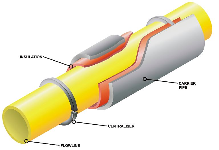
A pipe in pipe consists of a product carrying flowline that is installed within a carrier pipe. The space between the flowline and carrier pipe is known as the annulus. The annulus provides a dry environment that generally exists close to atmospheric pressure. This annulus allows insulation materials (e.g. polymeric PU foam, mineral wool, Porextherm Fumed Silica, Aspen Aerogel) that can be classified as non-marine to be used on the pipeline as they are not subjected to either moisture or hydrostatic pressure.
The attractiveness of pipe-in-pipe flowlines for deepwater is because they are simple to fabricate, use low cost proven materials, and because a high strength protective steel jacket offers nearly unlimited depth capabilities. However, the deepwater versions of these systems can be cost prohibitive for small or marginally economic fields.
The technical performance of the insulation materials should be considered in parallel with a costing of the insulation material. The overall cost of the insulation is not just a function of the material cost. The following factors should be considered when selecting an insulation material.
Insulation material cost.
Cost to apply material to pipe including the influence this may have on other fabrication activities such as welding rate and alternative fabrication procedures that may be applicable.
Potential reduction or increase of carrier pipe size based on different insulation materials.
Influence that alternative carrier pipe sizes may have on number of vessel sailings.
Influence that alternative carrier pipe sizes may have on pipe lay tension.
Requirement for centralisers.
Mineral wool insulation is a significantly cheaper insulation material than both Porextherm Fumed Silica and Aspen Aerogel, it is also likely to be much easier to apply to the pipeline.
However to achieve comparable OHTC values it will be necessary to have a larger OD carrier pipe. This will be more expensive in terms of steel quantity, welding time and it may result in a greater number of vessel trips. In cases such as these the higher more expensive insulation materials may result in a lower overall project cost. As an example Table 5.2.1 describes 3 systems that provide an OHTC (Uvalue) value between 0.7 and 0.9W/m²K.
The example case has been selected to show that improving insulation material can result in a reduction in carrier pipe size for a set of similar OHTC values.
For reel-lay installation, for a long deepwater pipeline requiring multiple trips to a field remote from the spool-base the Aerogel option is likely to be a more attractive proposal as the cost of insulation material will be small in relation to the fabrication costs and vessel transit times. Conversely for a short shallow water pipeline requiring a single pipelay trip the Porextherm or Mineral wool options become more attractive. The selection of the insulation material should therefore consider the overall effect that this will have on the pipeline design and alternatives should always be considered.
Polyurethane foam (PUF) insulation is one of the most common pipe in pipe insulation materials. PUF has been used successfully for both S-lay and J-Lay projects. However use with reel lay has been limited due to concerns over potential damage to the insulation during reeling.
The main thermal insulation materials that are normally considered for use with pipe in pipe are detailed below in Table 5.2, “Thermal insulation material for pipe in pipe system”:
Table 5.2 - Thermal insulation material for pipe in pipe system
Base material | Thermal conductivity | Density | Maximum Temperature |
(mW/m/°K) | (kg/m3) | (°C) | |
Low density polyurethane foam (EMERSON&CUMMINGS) | 25 | 70-500 | 100 |
High density polyurethane foam | 50 - 60 | 250-500 | 100 |
Mineral Wool (ROCKWOOL) | 34 (@ 20°C) | 100-120 | 700 |
Fumed Silica (POREXTHERM) | 19 (@20°C) | 190 | 150 |
Aerogel (ASPEN) | 13 (@20°C) | 110 | 200 |
5.2.2 Vacuum Pipe in Pipe
Drawing a vacuum in the annulus of a pipe in pipe is considered to have potential for providing insulation. There is no material cost associated with this system and a very small annulus gap is feasible allowing the outer pipe diameter to be reduced. This system is currently available, and commonly used, as insulated drill pipe. For drilling applications single joints of vacuum sealed pipe in pipe are supplied. Reflective (low emissivity) aluminium foil or Mylar is commonly included with vacuum insulation systems as the radiation component of heat loss can also be minimised. This will also be applicable for pipe in pipe where multiple layers of reflective foil will reduce the OHTC value. The disadvantage of this system is the practicality of achieving and maintaining a pressure low enough to provide a satisfactory level of insulation (typically below 0.1mbar). The ability to apply and maintain such low pressures over long pipeline lengths is unknown and presents the most significant challenge with vacuum systems.
5.2.3 Cryogenic Pipe in Pipe
Technip is evaluating the development of the LNG transfer from a platform to a remote offloading station. This offloading station is primarily a Single Point Mooring (SPM) system, which will ensure two functions:
The SPM can be a buoy (catenary anchor leg mooring type) or a small platform (steel jacket type) fitted in both cases with a turntable enabling the ship (moored by hawsers fastened to her bow) to freely turn around and remain head wind. A cryogenic flowline will connect the SPM to the platform, which can either be a LNG receiving terminal or a production plant located in shallow water.
This cryogenic line must feature an insulation performance similar to that required for large diameter LNG loading lines on land based LNG facilities (terminal or liquefaction plant). However, the conventional insulation system used on those lines (and also LNG carriers) i.e. large thickness of polyurethane foam (up to 160 mm) protected by a plastic vapor barrier is not suitable for such a subsea application. In this case, a robust casing must protect the thermal insulation, ensuring:
Hydrostatic pressure resistance which affords the use of light and high thermal insulation materials
A strong mechanical protection during installation and operation
A durable watertight barrier
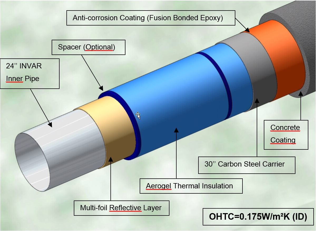
The pipe-in-pipe technology is particularly suited to meet the above basic requirements and has therefore been retained for this new application. The main components of the cryogenic pipe in pipe are given as follows:
Inner pipe
The inner pipe is made of Nickel alloy with 36% of Ni, commercially named INVAR. Because of its very low expansion coefficient and its low Young modulus compared to stainless steel material, the thermal stresses and strains resulting from the temperature difference are maintained low (approximately 10 times lower than stainless steel material). There is no need of artificial expansion devices (e.g. loops or bellows) due to the thermal or mechanical length variation. Combined with its high mechanical strength, high ductility, toughness and excellent welding properties, the INVAR material simplifies the design and fabrication for the production of cryogenic pipes.
Insulation material
The ASPEN AEROGEL thermal insulation is selected as the insulation material. AEROGEL are flexible nanoporous (e.g. monolithic Silica chain) insulation blankets designed to meet the demanding requirements of cryogenic applications. The flexible blankets are wrapped around the inner pipe and the length is calculated to fit its OD. The unique properties of very low thermal conductivity (13mW/mK at 20°C), good flexibility and ease of use makes the AEROGEL product essential to provide the ultimate in thermal protection within a reduced annular.
Outer pipe
The outer pipe is made of standard carbon steel. This material is designed to protect the internal pipe and insulation system. A concrete layer may be added for additional protection and/or stability.
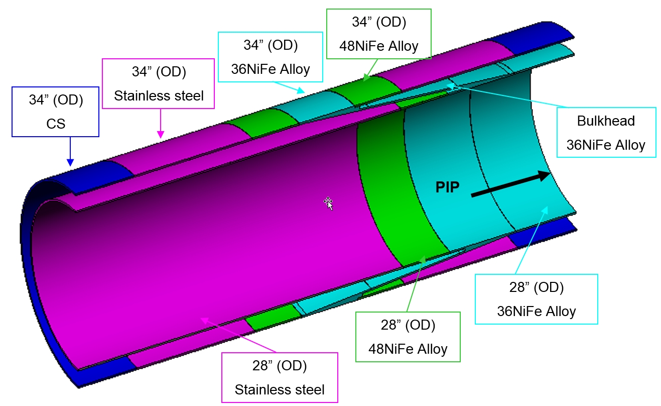
Bulkhead Designs
Pipe-in-pipe end bulkheads are placed at each extremity of the lines. The bulkheads seal the annulus area and transfer loads between the inner pipe and the outer pipe.
As for the inner PIP, the bulkhead is made of 36NiFe alloy and it is welded to a stainless steel pipe (or bend) at its extremities. The outer pipe material is carbon steel. Intermediate parts, made of special 48% Nickel alloy and stainless steel, are used between the bulkhead itself and the CS outer pipe. 48NiFe Alloy material features intermediate thermal expansion coefficient and hence allow for "smooth" transition. 48NiFe Alloy elements are also used to link the Invar bulkhead inner part to the stainless steel pipe.
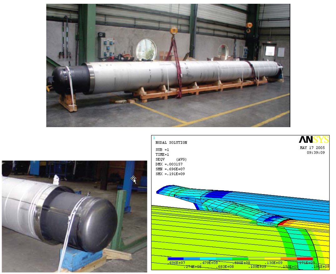
Technip has performed a comprehensive qualification test programme for the developed cryogenic PIP technology. Tests have been performed on full scale test pipe (26 Invar x 32 S/S, 10 m long) using liquid nitrogen, with a detailed engineering approach.
The objectives of the test programme are the followings:
To validate all industrial manufacturing processes: pipe manufacturing, bulkhead manufacturing, welding processes & procedures (TIG, plasma arc welding, automatic orbital welding), NDT tools and procedures, aerogel panels installation and fitting, spacers design / manufacturing and pull-in tests,
To validate the PIP mechanical behaviour, in particular validation of bulkhead design calculations (in particular the finite element analyses) with respect to thermal and pressure loads, pressure test at design pressure in cryogenic conditions and ambient temperature,
To verify PIP thermal insulation performance: measurement of temperature gradients, assessment of OHTC in cryogenic PIP conditions by measuring the produced boil-off, evaluation of bulkhead thermal bridge,
To obtain full Third Party Certification by a recognized Certification Authority (“Type Approval”).
5.3 Integrated Towed Flowline Bundle System
Where two or more flowlines, injection lines and electrical cables are connected to the same installation, they may be bundled in a common carrier pipe or outer casing. Bundles are fabricated onshore in lengths up to 16km and are towed to their accurate position that currently can be as deep as 1000m (Ensearch GC-388 in Gulf of Mexico) or 1400m (Girassol, West of Africa). Bundled constructions do have the advantage that all flowlines can be accommodated in a common insulation system, which can include additional pipes for heating medium circulation.
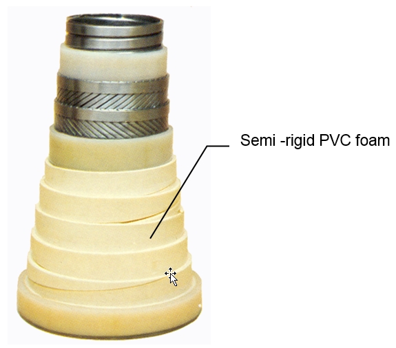
The carrier pipe is normally pressurised with dry nitrogen, allowing the use of low cost insulation materials such as rock-wool or low density PVC foam shelves with very low k-values of k=0.04W/m°K. Overall heat transfer coefficient as low as U=0.6W/m²°K can be achieved.
The use of heat insulating gel with a k-value of k=0.273 W/m°K can be offset against the more expensive conventional pipe insulation coatings. Gel will also provide adequate ballast for in-place stability, corrosion protection for the flowlines and internal surface of the carrier pipe. The gel is based on mono-ethylene glycol with heteropolysaccharide bio-polymer as a viscosifer and a chelating agent.
5.4 Flexible Pipe
Insulated flexible pipe used tape wound on the pipe to the necessary thickness to meet the insulation requirement (see Figure 5.6, “A sample of thermally insulated flexible”). The tape or flat sheet consists of hollow glass microspheres, in the size range of 100-200 microns, fibreglass macrospheres 0.124-0.5 inches in diameter and an epoxy, polypropylene, or polyester resin binder.
For high temperature application, Coflon watertight sheath placed around the interlocked layer is used as insulation material. This material is capable to withstand temperature up to 145°C. In general there is a limitation on the insulation thickness, due to the pipeline “on seabed” stability criteria and “Vault effects” occurred in crushing loads during installation phase.
For a 6”-8” ID flexible line, a typical thermal exchange coefficient U of 2.5-3.0 W/m²°K can be achieved with adequate insulation material.


