
9 Internal Corrosion Monitoring
9.1 Introduction
Protection pipelines from corrosion is achieved externally by use of cathodic protection (for buried or subsea pipelines) and internally by injection of inhibitors to mitigate internal corrosion. Various inspection and monitoring techniques monitor both a pipeline’s condition for early warning of failure and the efficiency of any mitigation program to reduce or arrest corrosion. While traditional NDT techniques and in-line inspection tools (intelligent ‘’pigs’’) may represent effective solutions for assessment of the condition and integrity of a pipeline, the sensitivity and accuracy of these methods may be inadequate for monitoring inhibitor performance. In this latter case, both the sensitivity and frequency of data collection must be high regularly to produce reliable trends.
Even more important to the pipeline operator may be the economics of an inspection and monitoring program. Suitable design of an NDT inspection and corrosion monitoring program may help reduce the expenditures considerably. A combination of monitoring of an actual pipeline with a certain number of Field Signature Method (FSM) stations along a line combined with running smart pigs through the line at infrequent intervals may represent an optimum solution in terms of condition and integrity monitoring of the pipeline. At the same time, such a program may be designed substantially to reduce the costs for inspection as a result of the reduced frequency required of smart pigging.
9.2 Principle
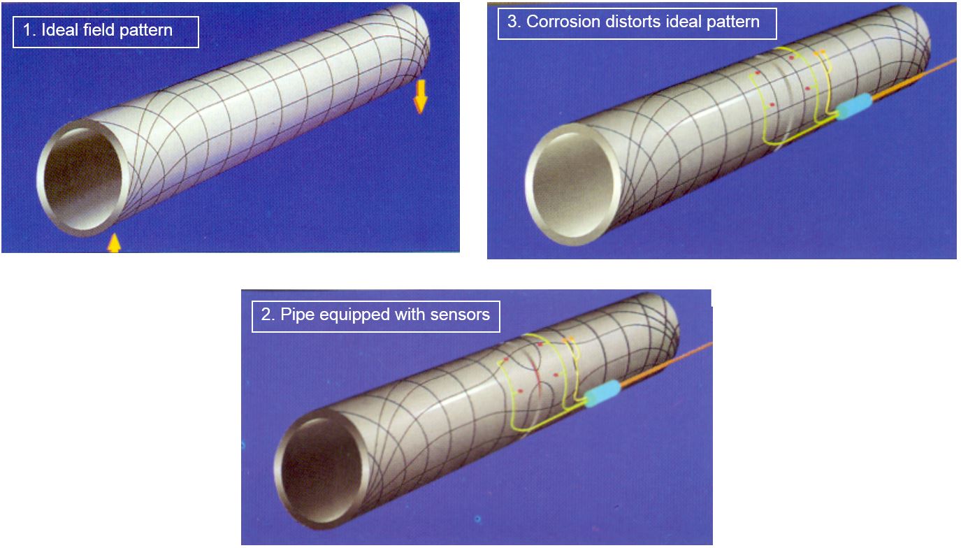
When a structure is in a known condition, reference FS (Field Signature) measurements are made by feeding an electric current into the structure between two feeding studs. The current spreads out into a pattern which is determined by the geometry of the structure and the conductivity of the material. Any flaws or defects in the structure, like a corrosion pit or a Crack will cause a distortion in the electrical field pattern. Also general corrosion, causing a reduction in the wall thickness will result in an increased voltage drop and change in the electrical field. By measuring this electrical field pattern and changes over a period of time, an accurate assessment can be made of actual corrosion, of corrosion rates and trends and the location and severity of pits and Cracks (see Figure 9.1, “Field Signature Method principle”).
Small sensing pins or electrodes are distributed in an array over the monitored area, to detect changes in the electrical field pattern. A voltage measurement between any two selected electrodes is compared to a measurement between a reference pair of electrodes (for compensation of temperature and current fluctuations) and to the corresponding initial FS values when monitoring started.
9.3 Arrangement of Sensing Pins
When designing an NDT or inspection program, the inspection engineer will select critical locations of a structure where the risks of corrosion, erosion or cracking are high or serious hazards might arise in the event of failure.
Typical areas chosen for monitoring are:
Girth welds of pipes and pipelines
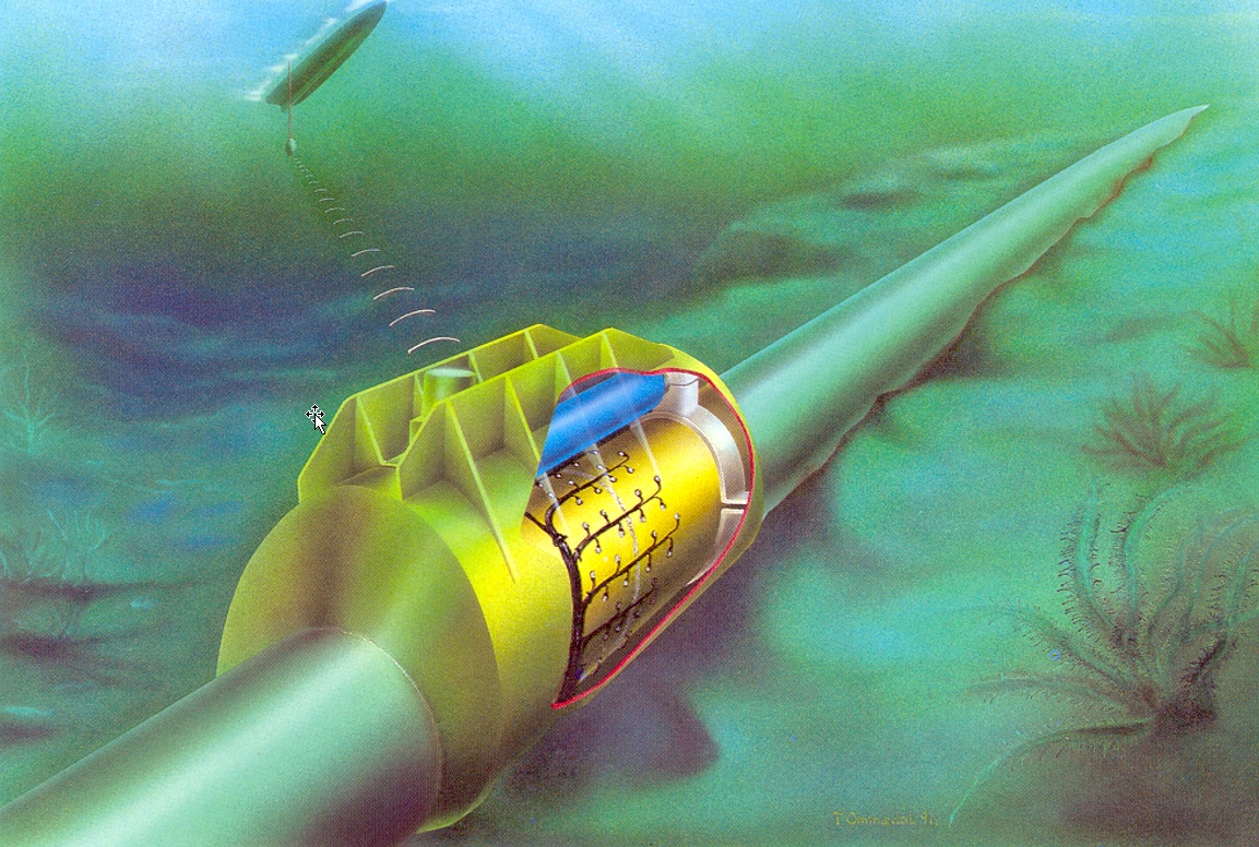
Bottom sections, e.g. at 4-8 o’clock position in horizontal pipes where corrosive water may be deposited (see Figure 9.2, “FSM applied to subsea pipeline” )
Combinations of the above, and area subject to corrosion induced by CO2, H2S or biological activity
T-joints of pipes where there is a risk for erosion/corrosion
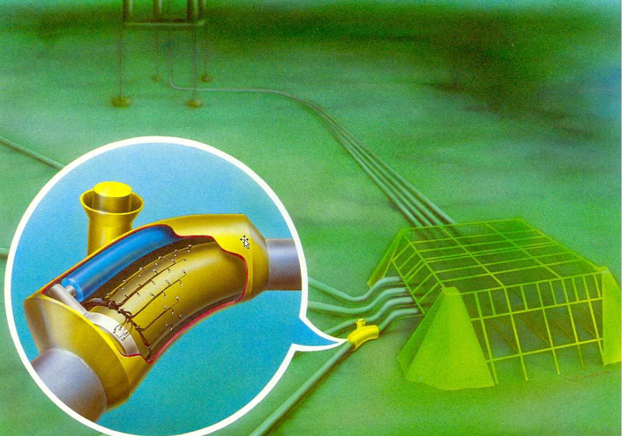
Pipe bends and welds (see Figure 9.3, “FSM applied to subsea production template”)
The selected area is fitted with the current induction transformer and the minimum number of 24 sensing pins. This number must however, be increased in multiples of 8 up to a maximum of 64 pins for one FSM spool and instrumentation module.
The sensing pins may be distributed in a matrix over the critical area where the matrix spacing or pin-to-pin distance may vary typically from 2-3 cm (1inch) up to 10-15 cm (4-6 inches), depending on the sensitivity required for detection of smaller pits. With a matrix spacing of 2-3 cm the system has a proven capability of detecting and monitoring the growth of pits in welds as small as 1-2 mm in diameter and depth. A matrix spacing of 10-15 cm is used in the case of uniform corrosion, or when wide and shallow Pitting is expected. Typical surface area covered per instrumented module may range from 0.1 to 1.1 m2.
9.4 Monitoring System
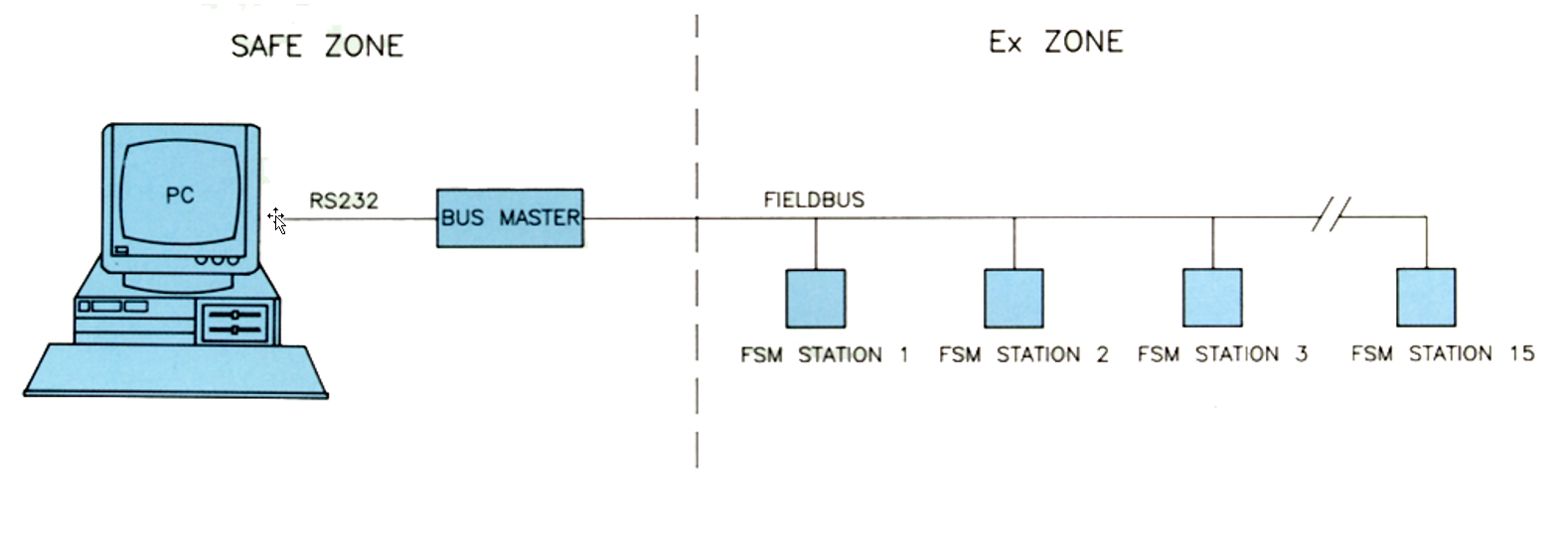
Permanent instrumentation systems for on-line monitoring are based on FSM stations to be fitted locally, one at each location, and connected via a field bus system to a Master unit in a control room. The Master unit can handle up to 15 FSM stations, and is controlled by an on-line monitoring software installed on a standard PC (see Figure 9.4, “Online FSM system based on field bus”).
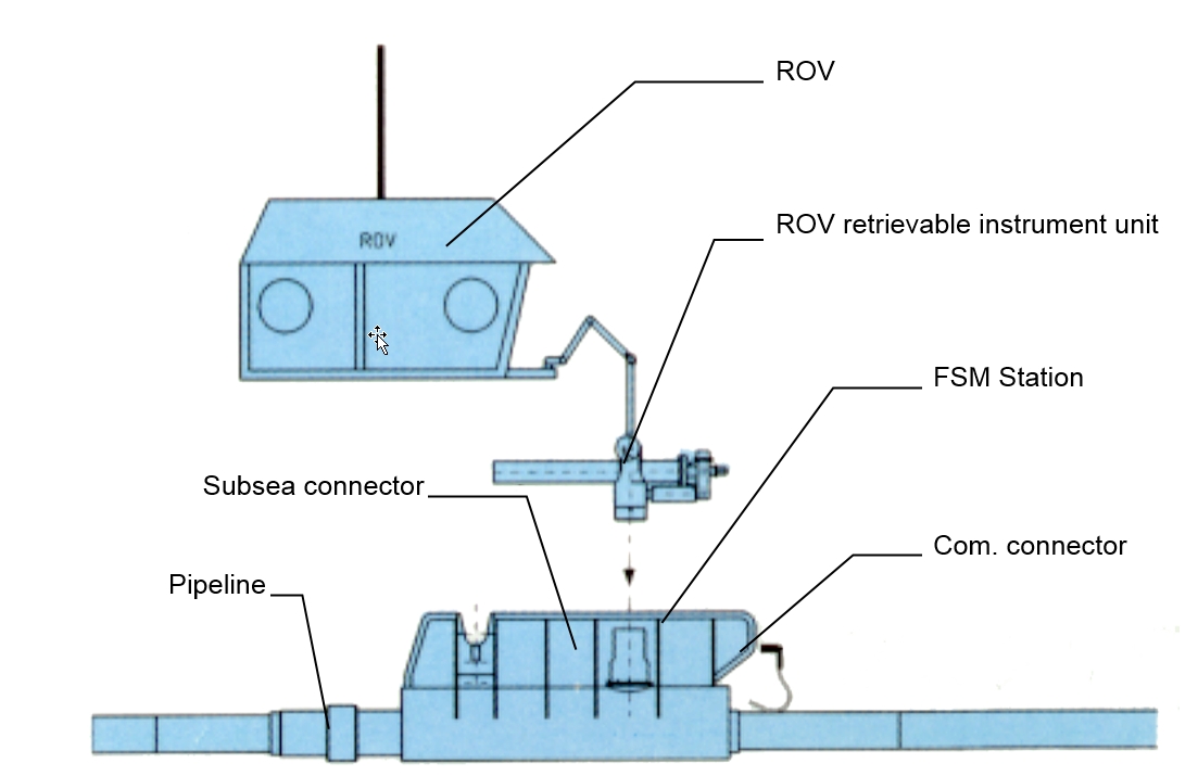
For subsea and remote monitoring, the FSM system can be supplied as ready made spools for subsea production systems or pipelines. The subsea system consists of the following components (see Figure 9.5, “FSM system in subsea remote monitoring”):
Instrumented pipe section with sensing electrodes, current feeding arrangement, reference electrodes and subsea mateable connector for the instrument unit
ROV replaceable instrument unit contains all electronics and batteries for many years of unattended operation. The instrument unit is hooked up to the instrumented pipe section via the subsea connector. Data communication alternatives are direct cabling or hydro-acoustic telemetry
Top-side data collection and storage unit, including the FSM software package.
9.5 Internal Corrosion Assessment
DNV-RP-F101 [12] provides recommended practice for assessing pipelines containing corrosion. Recommendations are given for assessing corrosion defects subjected to:
Internal pressure loading only.
Internal pressure loading combined with longitudinal compressive stresses.
The methods provided in DNV-RP-F101 [12] are intended to be used on corrosion defects in carbon steel pipelines (not applicable for other components) that have been designed to the DNV Offshore Standard DNV-OS-F101 [12] Submarine Pipeline Systems.


