6 Heating Techniques
6.1 Introduction
The seabed temperature at 100m water depth and deeper may range from -1.5°C to 7°C causing a rapid cooling of hot well streams being transported in subsea flowlines. At such low temperature vulnerable crudes and multiphase compositions will deposit wax and asphalt, and the gas - water phase may freeze solid hydrate particles that can permanently block the pipeline. A conventional approach to flow assurance has been to use thermal insulated flowlines in combination with the following measures:
Continuous injection of chemicals to reduce the hydrate freezing point and the rate of wax deposition
Depressurisation of the flowline to enable a further reduction of the hydrate freezing-point
Use of twin parallel flowlines to achieve a more effective depressurisation of pipeline, and to perform pig cleaning operations. Further to circulate hot water/oil in order to melt out wax and to pre-warm the flowlines after long shut downs.
It is obvious that these measures do have physical, economic and environmental limitations, especially in deeper waters and over very long transportation distances:
The pressure head in deep water pipelines may give an insufficient pressure relieve at blow downs
Blow down and depressurisation of pipelines will involve pressure drop expansions and a related Joule-Thomson supercooling of multiphase fluids, that by itself can cause severe wax deposits and hydrate formation.
Heat loss in long twin pipelines that shall be preheated in a serial configuration, will restrict adequate heating above 10-15km length
Continuous injection of large amounts of hydrate and wax inhibitors will dissolve in the produced water that may have a restricted release to sea
Long twin flowline installations will generate high investment and operational costs (e.g. OPEX).
Thermal insulated and electrically or hot water heated flowlines represent alternative prevention method for wax and hydrates that will not be restricted with the same limitations.
Subsea pipeline electrical heating is a relatively new technology in the Oil & Gas industry that has been developing, quite intensively during the last 15 years. There are two main techniques considered for subsea pipeline electrical heating; the first one, already deployed and in use, is direct Electrical Heating (DEH) and the second one, currently in the final stage of the technology readiness process, is Electrical Heat Tracing (EHT). Electrical heating of subsea pipelines is expected to be increasingly deployed as an elegant technical solution to optimize the flow assurance management during production pipeline’s service life and as a cost saving solution bringing significant reduction of projects overall CAPEX and OPEX
The heating techniques may be designed for the following purposes:
To maintain steady state pipe temperature above the hydrate formation temperature after planned or non-planned shutdowns,
Heating of the pipe, which have been cooled down to the ambient seawater temperature (long shutdown due to equipment failure),
To maintain the required temperature at low production rates.
Active heating technologies are widely field proven technologies for onshore applications in Oil Gas industry where the various constraints through the service life (power transport, space, maintenance, etc.) are more manageable than in subsea-offshore applications. Today onshore electrical heating systems have very low failure rates, mainly due to improved fabrication technology, new materials and requirements from various industry standards that must be met in order to be accepted as a viable solution in different Oil Gas market segments.
Industrial use of electrical energy for the heating started with the trace heating solutions begging the 1930's.. Mineral insulated cables were run at high current densities to produce heat, and control equipment was adapted from other applications. Mineral-insulated resistance heating cable
was introduced in the 1950's, and parallel-type heating cables that could be cut to length in the field became available. Self-limiting thermoplastic cables were marketed in 1971.
Control systems for the electric heating systems were developed from capillary filled-bulb thermostats and contactors in the 1970's to networked computerized controls in the 1990's, in large
systems that require centralized control and monitoring.
International standards applied in the design and installation of electric trace heating systems includes IEEE standards 515 and 622, British standard BS 6351, and IEC standard 60208.
Until now, these technologies have been commonly used for the following applications:
Pipe freeze protection in cold environment (Alaska, etc.): Pipes are insulated and an
electrical system is put on it, equipped with start/stop control logic. A thermostat is used to
energize the trace heating when it measures temperature falling below a set temperature
value - usually between 3°C and 5°C and often referred to as the 'set point'. The thermostat
will de-energize when it measures temperature rising past another set temperature value -
usually 2°C higher than the set point value.
Pipe temperature maintenance: The combination of trace heating and the thermal
insulation, appropriate to the ambient operating temperature, maintains a thermal balance
where the heat output from the trace heating matches the heat loss from the pipe. This
application is relevant to prevent pipe blockage.
Long line heating
Tanks, vessels heating such as storage tanks, etc.
Foundation heating (LNG tanks, etc.)
Snow and ice melting
Subsea Pipelines Electric Heating Solutions - Introduction
In order to help to solve mainly flow assurance issues, electrical heating technology entered offshore pipeline market at the end of the 1990’s with Statoil’s development of the first subsea Direct Electrical Heating (DEH) wet insulated pipeline for the Åsgard field some 200 km west of Nord-Trøndelag, Norway. Eventually the Åsgard world’s first DEH pipeline was installed in year 2000.
Following the DEH success, during the last 15 years two new electric heating solutions have been
introduced to the offshore pipeline market, each of them with different philosophy regarding the design, operability and efficiency, the first is DEH – PIP and the second is EHT PIP solution.
6.2 Direct Electrical Heating (DEH) – Wet Insulated Pipeline
6.2.1 Principle
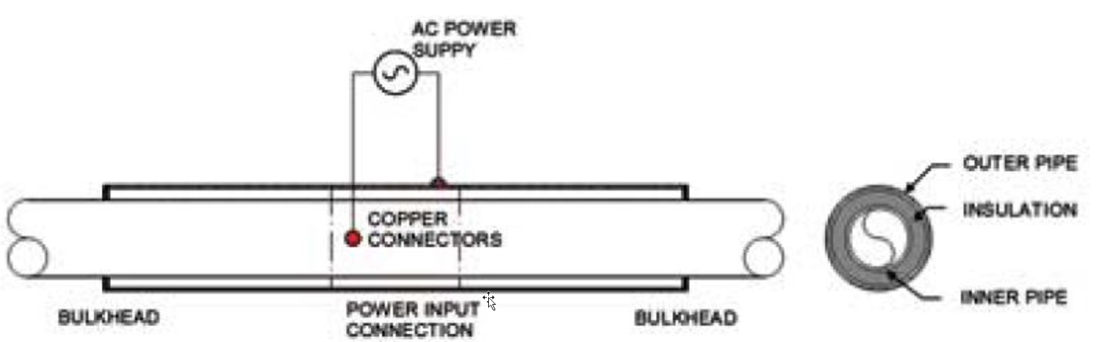
The technique is based on the fundamental principle that an electric alternative current (AC) in a metallic conductor generates heat due to Joule resistive effect. In the DEH system, the steel pipe wall is acting itself as a metallic conductor.
This system has been developed originally for pipeline with wet insulation.
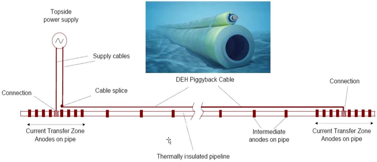
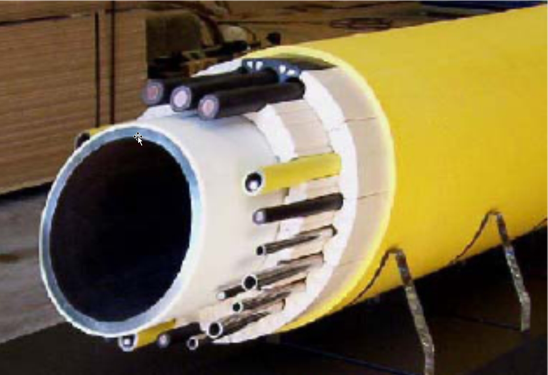
In the DEH system, the pipe to be heated is an active conductor in a single-phase electric circuit (AC), together with a single core power cable as the forward conductor, located in parallel with and close to the heated pipe (Figure 6.2, “Configuration Wet-DEH system”).
The heating system is supplied from the topsides power supply, from which two riser cables provide the electric power to the heating system. One of the two single core riser cables is connected to the near end of the pipe, and the other to the forward conductor, which is connected to the outmost end of the pipe.
The power rating of such a DEH system is dependent on many factors:
Pipeline characteristics (electric and magnetic data of pipe steel, pipe dimensions, pipe
insulation, length)
Design criteria (ambient seawater temperature, hydrate formation temperature, required
heating time)
Cable data (voltage, conductor cross section...)
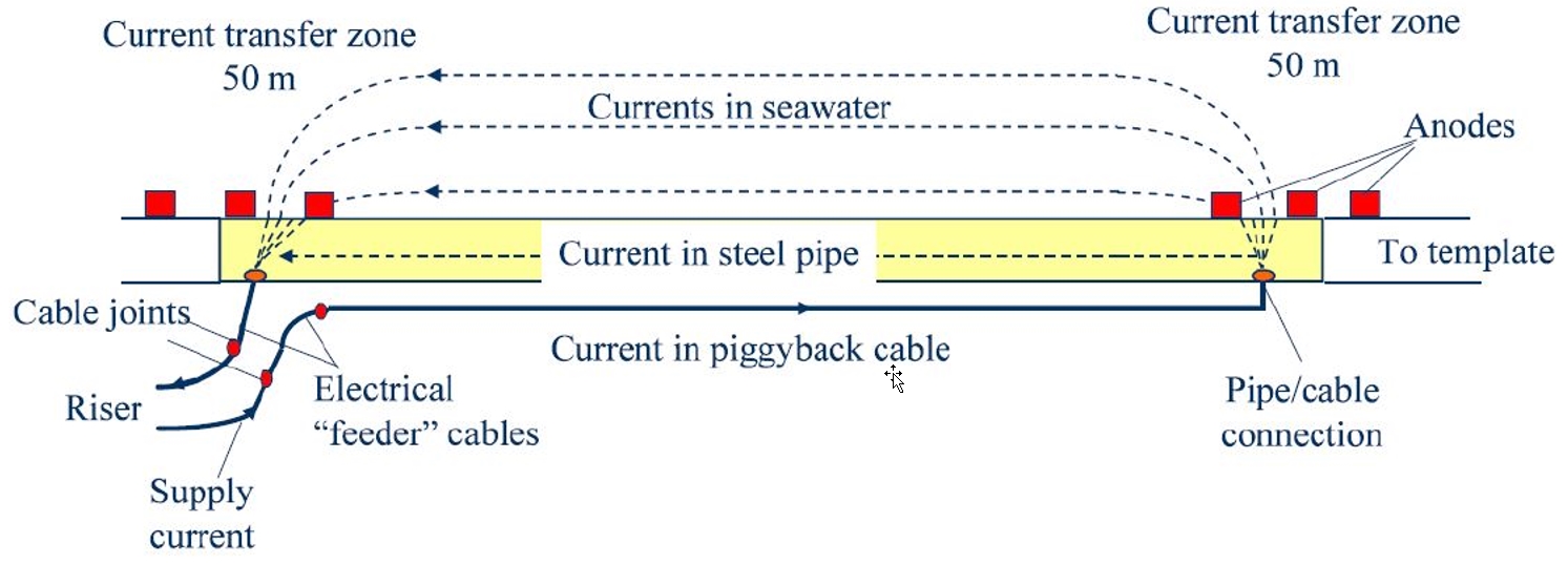
For safety and reliability reasons, the heating system is electrically connected (i.e. earthed) to surrounding seawater through several sacrificial anodes for a length of ~50m at both ends where
the cables are connected.
6.2.2 Track record
The DEH system has been developed initially within a Joint Industry Project (JIP) initiative in 1996-
1997 (Nexans Norway and Sintef Energy Research) based on a patent owned by Statoil.
For maintaining required production fluid temperature, so far DEH has been applied in nearly 20 different field-developments mainly in North Sea, Norway. The system has been successfully operated with operational experiences confirming simulated results and lab tests.
6.2.3 Advantages and drawbacks
The main advantages and drawbacks of the DEH for wet insulated pipelines are summarized in the
following table.
Table 6.1 - Advantages and drawbacks – DEH Wet insulated pipelines
Advantages | Drawbacks | |
Design |
|
|
Fabrication |
|
|
Installation |
|
|
System Efficiency |
|
|
Reliability/ Reparability |
|
|
6.2.4 Conclusion
The system heating efficiency is low as consequence of the pipe low thermal insulation capacity and low electrical efficiency that is estimated to be approx 60% (energy is lost mainly due to Joule effect in the DEH piggy-back cable and power lost in sea water). As such system is not preferred option for continuous heating solutions (high power requirements on topside).
On the other side system concept is field proven, robust, applicable for relatively long and big diameter pipelines that could be installed in any installation method (S-Lay, J-Lay or Reel Lay).
6.3 Direct Electrical Heating (DEH) - PIP
6.3.1 Principle
The system has been developed by Shell and is relevant for the Pipe-in-Pipe technology.
Originally, the DEH for Pipe-In-Pipe has been developed first as a tool for hydrate remediation; but
this technology can also be applicable for the heating of the flowline during field production
shutdown and / or for fields’ development (continuous heating).
The system is also called the “Electrical Heating Ready System” and its principle is as follows:
Production line is split into heated segments (each segment is equivalent to a close electrical circuit composed of inner and outer pipe).
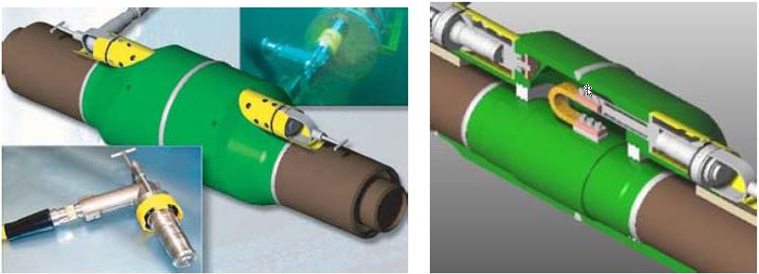
Each heated pipe-in-pipe segment is terminated at both ends with a steel bulkhead (Figure 6.5, “Mid-Line assembly (MLEC) of Shell DEH PIP”) in order to have a closed electrical circuit.
A plug-in high-voltage high-amperage electrical connection can be made in the center of the flowline segment at the Mid-Line Electrical Connector (MLEC, Figure 6.5, “Mid-Line assembly (MLEC) of Shell DEH PIP”:).
Current will flow from the MLEC in both directions through the inner pipe wall, via the bulkheads, and back through the outer pipe wall.
Skin effect and proximity effect keeps the current on the outside of the inner pipe and inside of the outer pipe, so there is no risk of current leakage to the environment, with associated corrosion problems.
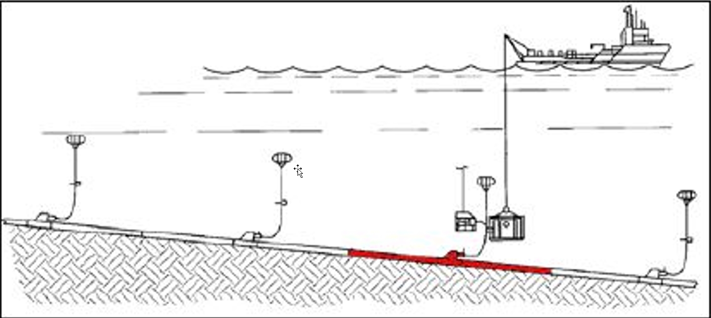
If an hydrate plug forms in one of the segments, an electrical heating spread will be mobilized to the field to heat up this segment in a matter of days. The heating spread includes (Figure 6.6, “DEH PIP – Heating Spread on one segment – Plug remediation”):
A subsea transformer with flying leads,
An umbilical and reel,
A surface switch gear,
A generator on a vessel of opportunity.
Compared to the DEH system coupled with wet insulation, this solution presents higher power
efficiency for the following reasons:
There is no communication with the seawater, thanks to the skin and proximity effects,
The thermal losses are decreased, thanks to the PIP insulation.
However this system requires specifically designed components such as non-metallic bulkheads and seems limited to medium lengths: longer lengths would lead to higher voltage and large annulus width for electrical isolation purposes.
6.3.2 Track record
The track record of this solution is limited to three Shell’s projects where the heating system was designed for remediation on-demand only.
In Serrano/Oregano development, 20 shutdowns have occurred between 2002 and 2007 and, each time, the heating system has been used successfully.
6.3.3 Advantages and drawbacks
The main advantages and drawbacks of the DEH for PIP are summarized up in the following table.
Table 6.3 - Advantages and drawbacks of the DEH technology for wet insulated pipes
Advantages | Drawbacks | |
Design |
|
|
Fabrication |
|
|
Installation |
|
|
System Efficiency |
|
|
Reliability/ Reparability |
|
|
6.3.4 Conclusion
The system heating efficiency is high as consequence of the PIP high thermal performance with low electrical estimated to be up to 70%.
System is not preferred option for continuous heating solutions.
On the other side system concept is field proven, robust, and pipelines could be efficiently installed in J-Lay or Reel Lay installation methods.
6.4.1 Principle
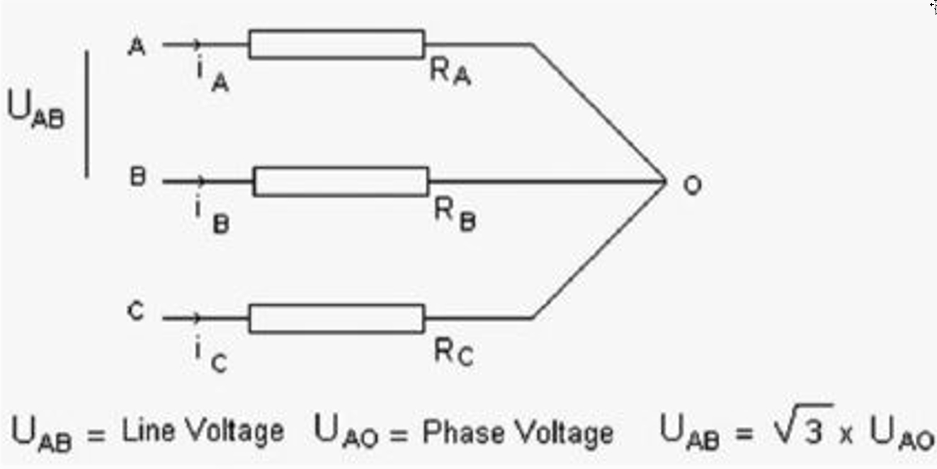
EHT PIP system has been developed during the last 10 years, with 3-phase insulated trace
heating wires installed around the inner pipe under insulation layer in PIP annulus and terminated
in star end connector (see Figure 6.7, “Three-phase star configuration.”). The Joule resistive effect of these 3-phase electrical wires
attached to the production generates heat which is then transferred to the inner/production pipe by
conduction.
The use of EHT PIP for max size pipelines (ID 12in) is at the moment limited to relatively short distance (up to 25km) with use of low to medium voltage (1 to 3.6kV) cables. For EHT PIP temperature monitoring and control along the whole pipeline length is added fibre optic cable (FOC) as integrated part of the system.
To extend the use of such systems, there are several possibilities:
Multiplication of the number of cables,
Reduction of the heating power per meter by use of high-performance insulation
technologies,
Regular power re-alimentation of the heating system.
Qualification of new equipment (high power cables and wet mate connectors)
The EHT PIP is currently qualified only for reel lay or towing installation method. This installation method appears as the most relevant for this heating technology as number of wire field slices is minimized. Nevertheless, reel lay is suitable only for limited inner pipe diameters up to 12”, so the installation of larger inner/production pipes will require use of other installation methods.
6.4.2 Advantages and drawbacks
The main advantages and drawbacks of the EHT- PIP are summarized up in the following table.
Table 6.4 - Advantages and drawbacks of the heat tracing technology
Advantages | Drawbacks | |
Design |
|
|
Fabrication |
| |
Installation |
|
|
System Efficiency |
|
|
Reliability/ Reparability |
|
|
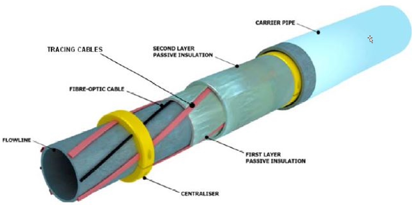
6.5 Flexible : Integrated Production Bundle
Integrated Production Bundle (IPB), has been designed, manufactured and installed for Dalia field in West of Africa (1400m water depth).
The IPB is a flexible riser assembly incorporating active heating, gas lift hoses, monitoring fibre optics and passive insulations. The integrated heating system is proposed to prevent hydrate blockage by maintaining a minimum bundle temperature. It can be considered as a riser concept to face stringent flow assurance requirement. Typical power input required range between 100W/m to 300W/m.
An IPB (see Figure 6.9, “Integrated Production Bundle (TECHNIP)”) comprises primarily the following components:
The core, which is a ‘standard’ flexible pipe structure for production fluid transportation
The external assembly which is a bundle of tubes, hoses, cables and fillers wrapped in ‘SZ’ configuration around the core.
The insulation material is typically syntactic polypropylene foam. The insulation layers can either be made of spiralled strips or either made of thick fillers assembled in S-Z around the core structure.
Further information is provided in the document - Riser Systems - [77].
Kvaerner have qualified the IPU (Integrated production umbilical), which can be described as a bundle with a solid central rigid bore pipe, with a range of peripheral gas lift steel tubes, trace heating (mainly SECT tube based) lines inside the insulation layers. A simplified description of the system would be similar lay out than a flexible pipe / umbilical, i.e. requiring its complexity of assembly but with the constraints of offshore installation of a rigid pipeline. Similar power requirements than for an IPB are expected. The system has completed its qualification by DNV and is planned to be installed on the Shell Merganser / MC920 project in the GOM.