
4 Pipe line Technology Review
4.1 Introduction
The following pipeline material and technology are readily available:
Material:
Carbon-Manganese steel pipe
Duplex and Super Duplex stainless pipe
Stainless steel
INVAR (36% nickel steel alloy)
Technology:
Wet insulated rigid pipe
Flexible pipe
Pipe-in-pipe system
Pipeline bundle system
Clad pipe system
CRA lined pipe system (CRA mechanically bounded to steel)
CRA claded pipe system (CRA metallurgically bounded to steel)
High density polyethylene internal liner
![[Tip]](tip.png) | Tip Click these links below for access to 3D resources: |
4.2 Standard Line Pipe Specifications
There are a number of standard linepipe specifications in use, and for the oil and gas industry the main pipe specifications are:
API 5L – Specification for line pipe
API 5LC – Specification for CRA linepipe
ISO3183 part 3 - Petroleum and natural gas industries – Steel pipe for pipelines – Technical delivery conditions – Pipes of requirement class C.
DNVGL-ST-F101- Submarine Pipeline Systems
The standard linepipe specifications define minimum requirements for the supply of linepipe for oil and gas applications and cover the following requirements:
Manufacturing process
Material chemical composition and mechanical properties
Pipe dimensions, tolerances, end finishing and defects
Inspection and testing requirements
Markings of pipe.
The standard linepipe specifications define the ranges of standard dimensions (diameter and wall thickness) and standard mechanical properties. The diameter for linepipe is standardised on the outside diameter with the inside diameter varying as a function of wall thickness. It is possible to procure pipe to non-standard dimensions, although this could have cost implications. Standard mechanical properties are defined in the linepipe standards. For the pipeline designer, choice of the material grade and defining yield stress (specified minimum yield stress, SMYS) and ultimate tensile strength are of particular interest. The standard material grade designations for carbon-manganese steel, based on API 5L are shown in Table 4.2 below.
Table 4.1 - Linepipe grades (C-Mn steel)
API 5L Grade | SMYS (MPa) | UTS (MPa) | Corresponding ISO 3183-3 grade |
B | 241 | 413 | L245 |
X42 | 289 | 413 | L290 |
X52 | 358 | 455 | L360 |
X60 | 413 | 517 | L415 |
X65 | 448 | 530 | L450 |
X70 | 482 | 565 | L485 |
X80 | 551 | 620 | L555 |
API 5L X70 is the highest strength linepipe seen in widespread use although higher grades have and are being used.
Sour Service
Where sour service is specified, additional material requirements are specified to prevent environmental cracking, such as hydrogen induced cracking (HIC) or sulphide stress corrosion cracking (SSCC). In such applications, the additional requirements of NACE standard MR-01- 75 “Sulphide Stress Cracking Resistant Metallic Materials for Oil Field Equipment” are often specified.
The general requirements of this NACE standard are embodied within ISO3183 part 3. Materials shall be selected to be resistant to SSCC if the system pressure is 4.5 bara (65psia) or greater, and if the partial pressure of H2S is greater than 0.0035 bara (0.05psia).
DNVGL-ST-OS-F101
Where [13] is used as the design code, the minimum linepipe requirements specified within the code must be complied with. In addition to the basic specified requirements, there are a number of supplementary material requirements to address specific applications. The supplementary requirements address:
P – Linepipe for plastic Deformation.
U – High utilisation.
D – Enhance Dimensional Requirement for Linepipe.
S – H2S service.
F – Fracture arrest properties.
The following sections will further describe the above material and technology.
4.3 C-Mn Steel Pipe
Currently, most line pipe steels are made by either basic oxygen or electric-arc furnace steelmaking. Another steelmaking process called open-hearth steelmaking, should be avoided because it doesn’t allow for the production of clean and low-carbon steel. The two former processes can produce line pipe steel of acceptable quality.
4.3.1 Steelmaking Process:
The making of steel by the basic oxygen process or in an electric-arc furnace can result in material with lower carbon and lower sulfur contents. Materials with lower carbon contents have lower ductile-to-brittle transition temperature and are more readily weldable. Reduction in the sulfur content tends to reduce the occurrence of elongated non-metallic sulfides. The latter are quite detrimental to ductile toughness and are especially detrimental in skelp destined to make into electric resistance welded (ERW) line pipe or in any material that may be exposed to H2S in service.
Aside from the steelmaking process, a producer may also employ ladle processing to further reduce the sulfur content and to introduce beneficial alloying elements. In most cases the molten steel in the ladle, shrouded from contact with air, is poured into a continuous slab or strand caster. These casters allow the steel to solidify at the outside surface while remaining molten internally to a point below the ladle outlet. The internally molten steel may be stirred magnetically or subjected to ‘’soft reduction’’ to prevent alloy segregation. Spray cooling is used to lower the temperature of the slab or strand as it is gradually curved into a horizontal position. A resulting slab is sent to a hot-rolling mill ; a strand is generally cut into billets for making seamless pipe.
4.3.2 Seamless or Seam Welded Pipe
Most line pipe is made as seamless, electric-welded, or furnace butt-welded pipe. Furnace butt-welded pipe is so limited in size and grade that is not a practical method for making pipe for high pressure pipelines. Therefore, the practical choices evolve to seamless and electric-welded pipe. The seams of electric-welded pipe may be electric resistance welded (ERW) or submerged-arc welded (SAW). Other seam welding processes (Gas metal arc welding MIG, combination of gas metal arc welding and submerged arc welding) are recognised by API specification 5L, but they are apparently not widely used.
Seamless pipe:
Seamless pipe is made one round at a time from single billets by one of several possible multi-step hot-forming processes. However the general process is practically the same:
Heating of cylindrical or parallelepipedic billets up to 1300°C
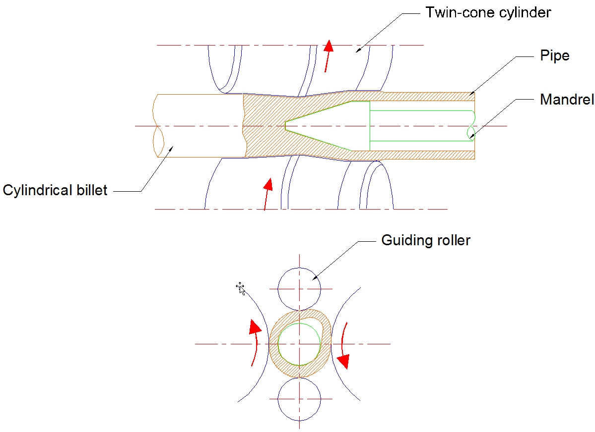
Piercing of billets (1150 – 1250°C) (Figure 4.1, “Billet piercing process”)
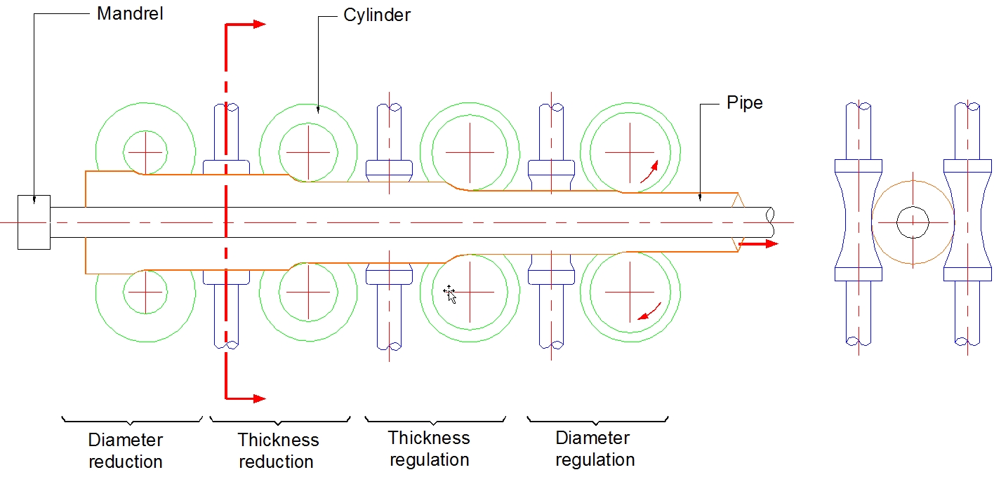
Lamination at 1000 – 1100°C to obtain the required thickness (Figure 4.2, “Continuous lamination”)
Final calibration (800 – 900°C) to fixe the external diameter
Cut from the resulting pipe (12m long or more) to the desired length
As a result it is generally more expensive, than welded pipe. It is made in sizes ranging from 2 3/8-in diameter through 24-in diameter and in grades from Grade A through Grade X65. It may be obtainable in higher grades (X80-X100) but such materials may require special heat treatment. If so the cost will likely be quite high relative to welded pipe.
The seamless pipe is the pipe of choice for deepwater field development due to more and more demanding applications (water depth, HP/HT) and performance (lay tension, plastic Deformations). These set limitations for pipe not only in its mechanical properties (material hardness, limited yield variation, maximum yield/tensile ratio) but also in the area of diameter and pipe wall thickness tolerances and non-destructive testing.
The metallurgical aspects of heavy wall high-strength seamless pipes are important criteria to determine the optimum combination of strength and toughness for deepwater applications.
The optimised chemistry (homogeneous microstructure) and the correct process of quench and temper (Q&T) will provide heavy wall pipe with increase strength without reducing toughness.
The main stage of the process are hot piercing, hot rolling at a retained mandrel mill, and sizing. The subsequent Q&T consists of a first heating up (austenitisation), internal and external quenching, followed by a second pipe heating (tempering).
In this process, optimum combinations of carbon (C), manganese (Mn), chromium (Cr), molybdenum (Mo), nickel (Ni) and microalloying elements (Nb, V, Ti) are to be obtained for optimum strength and toughness seamless pipe.
Electric resistance welded pipe:
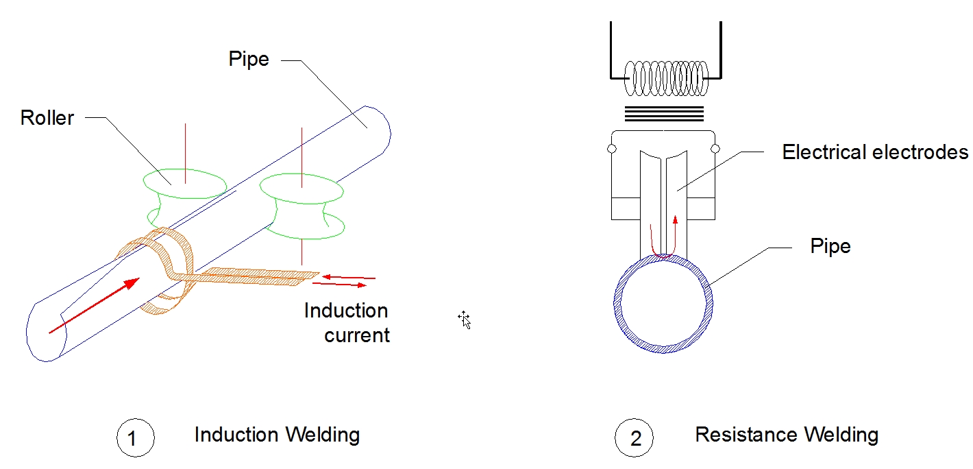
ERW line pipe is made from coiled skelp in a continuous process where the strip is edge trimmed and cold-formed from its initial flat condition into a round shell. As the edges of the strip are brought together electric current is passed between them heating them locally to the point of melting or near melting just as they are forced together by a pair of rollers bearing on the unheated portion of the shell (see Figure 4.3, “Electric Resistance/Induction Welded pipe”). The pressure forces the heated edges together, upsetting excess material to the outside and inside. The excess ‘’flash’’ is trimmed from both surfaces. In most ERW processes the just-completed weld zone is then immediately subjected to post-weld heat treatment. The weld zone is reheated to a temperature which ‘’normalises’’ the microstructure in the area of the bondline minimising or eliminating possibly unfavourable microstructural components created during welding. Pipe segments of the desired length are then cut from the continuous tube. In a few ERW mills the finished tube is subjected to ‘’full-body’’ normalising where the whole tube is heated to the normalising temperature. In either case the pipe is sized by passing it through rolls. ERW line pipe is obtainable in sizes ranging from 2 3/8-in diameter through 24-in diameter and in grades ranging from Grade A through Grade X70. A few manufacturers may offer Grade X80 ERW pipe.
However, ERW pipe is not commonly used in deepwater applications.
Submerged arc welded pipe
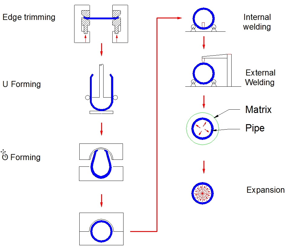
The third type of line pipe is that made from individual plates with a submerged-arc welded seam. Typically, very large diameter, heavy-walled line pipe materials are made by this process. The process begins with the plates being squared at the ends and edge trimmed and bevelled along the long edges. The plates are then cold-formed into ‘’cans’’ roughly 40-feet in length. In some cases the cans are formed in stages including edge-crimping, U-ing (forming to a U shape) and O-ing (pressing the cans to a round shape). U-O pipe is generally cold-formed (expanded) to its final size after being seam welded by mechanical or hydraulic means (see Figure 4.4, “Submerged Arc Welded pipe fabrication process”). In other cases the cans are formed by means of pyramid rolls and the pipe is sized after being seam welded by means of rolls in much the manner as ERW pipe is sized.
The seam-welding of SAW pipe is done in two passes both in the flat position, one from the ID side and one from the OD side. Usually the ID pass is made first by means of a three-to-five wire welding head. The pipe is then turned 180 degrees, and the OD pass is made with a two or three-wire welder. No post-weld heat treatment is required. Factors which can affect quality are the filler-metal chemistry and flux chemistry and the manner in which the first pass is made. Holding the edges in the proper position and preventing relative movement while the first pass solidifies are essential. For this reason some manufacturers tack weld the edges of the cans prior to seam welding. Others rely solely on mechanical restraint.
Straight-seam SAW pipe is obtainable in sizes ranging from 16-in OD through 48-in OD (larger sizes may be available from manufacturers in Europe or Japan) and in grades from Grade A through Grade X70. Grade X80 materials may be available through certain manufactures. SAW
pipe is also obtainable with a spirally-oriented seam (see Figure 4.5, “Spirally-oriented seam welded pipe”).
In this process, the plates are welded end-to-end so that a continuous strip is fed at the proper prearranged angle to a forming stand. The spiralling strip is then continuously welded along the incoming edge into a round tube. Both an ID and an OD pass are made. Pipes of the desired length are then cut from the resulting continuous tube. Finally, if the pipe is to be coated with fusion-bonded epoxy, the pipeline surface condition should be suitable for coating. The main problem to be avoided is surface slivers which, when raised by grit blasting and heating, cause severe coating defect problems.
In deepwater applications, SAW pipes are not commonly used except in bundle configuration where the carrier pipe may be made from SAW pipe as a cost effective alternative to seamless pipe.
4.3.3 Main Steel Pipe Manufacturers
The main steel pipe manufacturers are:
Vallourec (Europe)
Tenaris (Argentina)
US Steel (USA)
Nippon Steel and Sumitomo Metal (Japan)
JFE Steel Corporation (Japan)
TATA Steel (India)
4.4 Flexible Pipes
There are mainly three (3) flexible pipe manufacturers listed below:
TechnipFMC (France)
Wellstream (USA-UK)
NOV (Danemark)
Flexible pipes have been extensively used in Brazil Campos Basin since 1977. The world deepest application (2007) is to be reached on Roncador field at 1800m-1900m.
The structure of a typical flexible pipe (e.g. Technip) is shown in Figure 4.6, “Typical flexible pipe structure for oil production and transportation”:
The various layers constituting a typical flexible pipe are detailed hereafter, from the inside part of the pipe to the outside:
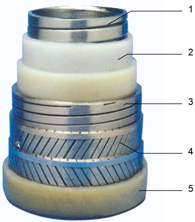
Interlocked steel carcass (made of profiled stainless steel strips): to provide mechanical resistance to radial forces either from internal pressure, hydrostatic collapse or crushing loads, and to resist wear resulting from the use of scraper pigs and Through Flow Line tools.
Pressure plastic sheath (e.g. made of polyamide): to make the flexible pipe leak proof and immune to corrosion. The material used depends on the characteristics of the conveyed fluid (e.g. type, temperature, pressure, etc.) and the working conditions of the pipe (e.g. static, dynamic, etc.)
Zeta or Teta spiral ( made of Z-shaped or T-shaped carbon steel wire wound around the inner layer): to resist to hoop stress due to the internal pressure and to external crushing loads
Armours layers (made of two or more cross-wound layers of carbon steel wires): to provide the high tensile strength of the pipe whilst also acting as a weighting layer which can be adjusted to meet particular stability requirements. Moreover, they give remarkable torsional stability
External plastic sheath (e.g. made of grade of polyamide): to prevent corrosion or abrasion of the metallic layers inside the structure and to bind the under layer of amours. It is a continuously extruded thermoplastic layer which prevents build-up of marine growth.
![[Note]](note.png) | Note
|
The following figure sets the flexible pipe water depth limitations (typical), and further details on flexible pipe technologies and applications are provided in document [77].
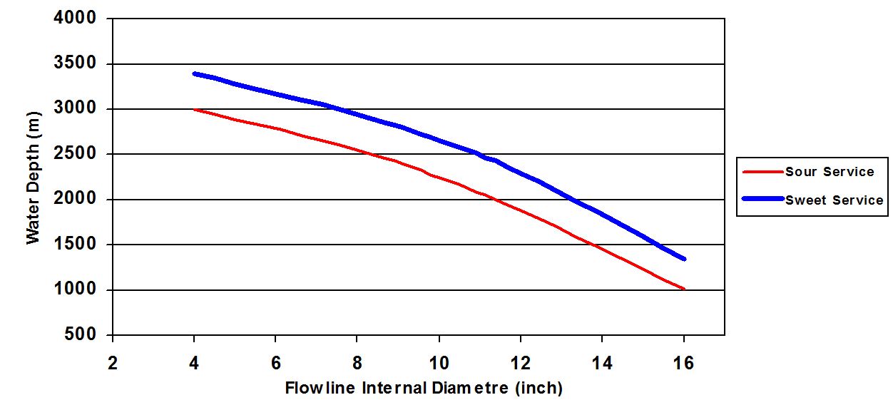
| Note Maximum water depth based on the following basis,
|
4.5 Stainless Steel
When the use of carbon steel is not possible because:
high corrosion rates are expected ; consequently high corrosion allowances are necessary,
corrosion inhibition is not feasible
a coating cannot be used
then stainless steel must be considered. Two of the most widely used methods to produce stainless steel pipe are shown in Figure 4.8, “Different types of stainless steel fabrication process”.
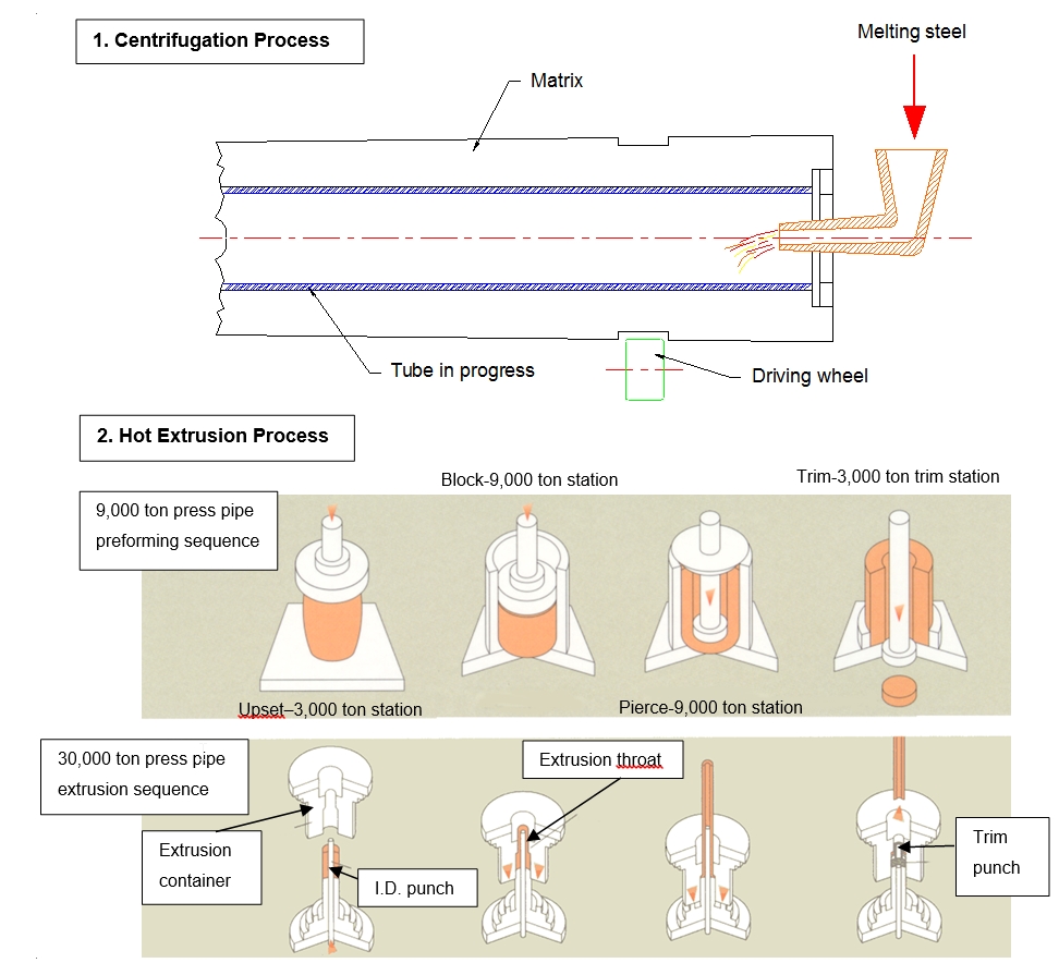
The seamless hot-extruded pipe is produced on the 30,000 ton hydraulic press in the range of 150 – 1200mm Diameter, 10 – 200mm Wall Thickness and 16 metre maximum individual length.
It is desirable that the material should be easily welded. This means, in terms of corrosion, that the weldments must exhibit mechanical properties and a corrosion resistance similar to the base material.
13% chromium steel, widely used for wells to mitigate against CO2 corrosion in the absence of H2S, is much less utilised in surface installations. Austenitic Stainless Steel type 316L (very low carbon content or stabilised to avoid intergranular corrosion) and the various austenitic-ferric steels (Duplex) have a better weldability and above all a better corrosion resistance than 13% Cr steel.
However, they are very sensitive to corrosion Pitting. An intensive welding qualification programme has been set up for the Asgard project to allow the implementation of 13%Cr steel as flowline material.
The use of these materials for flowline is viable even though the cost is greater than carbon steel.
4.6 Invar
For cryogenic application, the characteristics of Liquefied Natural Gas (LNG), in particular its temperature of -163°C and the large volumes involved, means that traditional materials used for the manufacturing of pipelines for offshore use in the Oil and Gas industry are not acceptable, and that alternative materials must be used as Nickel alloy with 36% of Ni, commercially named INVAR. Because of its very low expansion coefficient and its low Young modulus compared to steel material, the thermal stresses and strains resulting from the temperature difference are maintained low (approximately 10 times lower than steel material).
There is no need of artificial expansion devices (e.g. loops or bellows) due to the thermal or mechanical length variation. Combined with its high mechanical strength, high ductility, toughness and excellent welding properties, the INVAR material simplifies the design and fabrication for the production of cryogenic pipes.
4.7 CRA Lined or Claded Pipe System
The need for transport unprocessed corrosive multiphase well streams has increased interest in CRA lined or claded flowlines as an alternative to installing inhibited carbon steel.
Handling unprocessed corrosive fluids then raises the issues of reliability, safety, and the costs of possible failures.
Although the initial capital costs of a claded/lined pipeline are quite high, the subsequent operating costs over the life of the project are relatively low. The opposite is true for carbon steel where relatively low initial costs may be coupled with significant operating and repair costs. For this reason, a life cycle cost analysis provides a better measure of the overall costs of clad versus carbon steel flowlines.
4.7.1 Manufacturing Procedures
There are different manufacturing processes for CRA lined or claded pipe:
Hot rolling process, coextrusion or explosive bonding (metallurgically bonded : CRA claded pipe)
Thermo-hydraulic fit method (mechanically bonded : CRA lined pipe)
TThere are two methods for the hot rolling process (main process for CRA claded pipe):
Thermo-mechanical control process to clad pipe
As-quenching type heat treatment on welded clad pipe
These processes and methods are described hereafter:
4.7.2 Hot Rolling Process:
Figure 4.9, “Hot rolling clad pipe manufacturing process” shows typical hot rolling clad pipe manufacturing process.
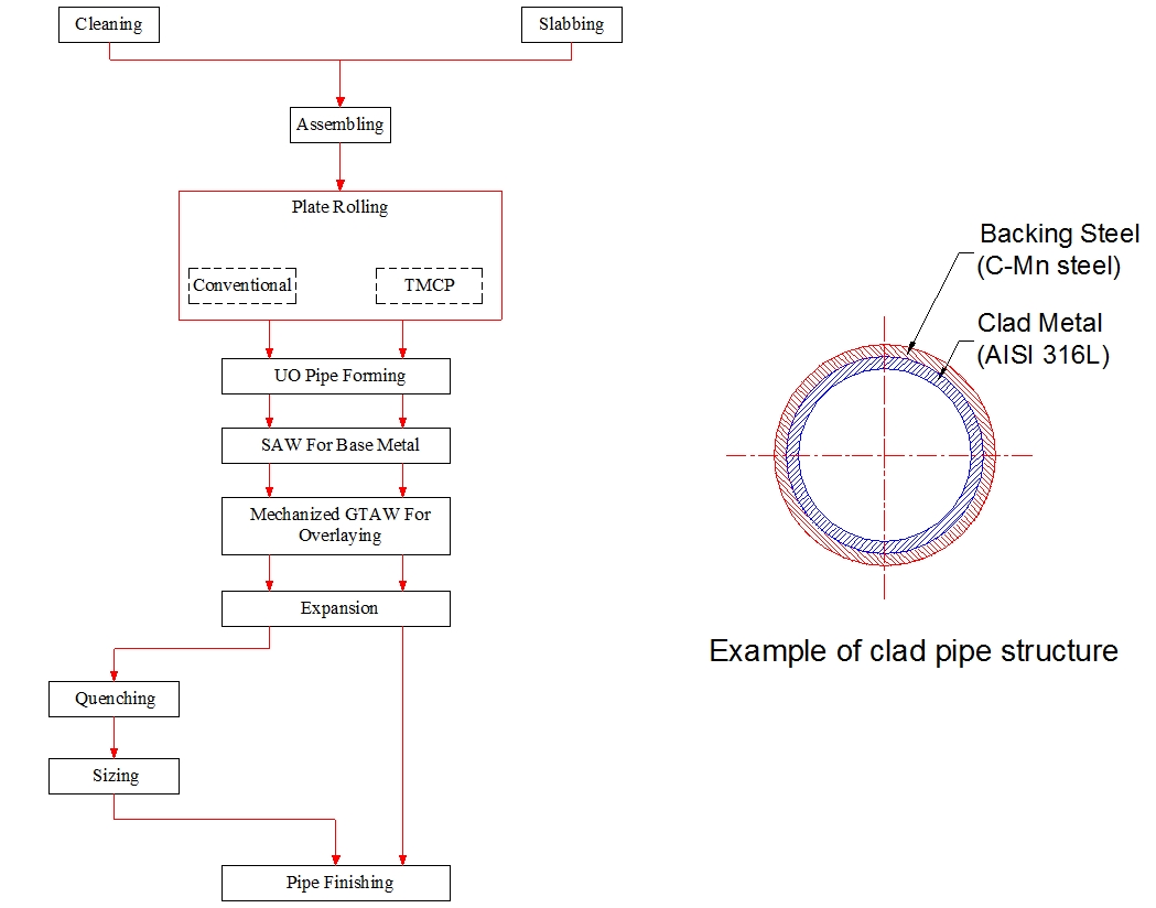
In the clad pipe manufacturing process, the clad metal and the backing steel are metallurgically bonded by hot rolling process after slab assembling.
Two types of rolling processes are used:
One is the application of the thermo-mechanical control process to clad pipe, in which no heat treatment is applied on the clad plate or the welded clad pipe (TMCP plate process)
The other is conventional rolling process with as-quenching type heat treatment on welded clad pipe by induction heating in a short time (pipe quenching process). The selection from these two processes is determined by taking account of the cladding materials and required properties.
In the application of TMCP to clad plate rolling, it becomes difficult to obtain both high strength and good toughness of backing steel when wall thickness is increased. As-quenching type heat treatment on welded pipes is useful for heavy wall thickness or superior toughness requirement. Quenching from relatively high temperature is also effective to improve corrosion resistance of the clad metal even if the corrosion resistance is deteriorated by hot rolling or longitudinal seam welding.
Longitudinal seam welding procedure consists in first welding backing steel by submerged arc welding (SAW) with one pass in each side, and next performing an overlay welding in two molten pools by tandem Gas Tungsten Arc Welding (GTAW) with the hot wire method.
Finally, inner surfaces of welded clad pipes are polished with wet brush to remove weld scales and to smooth the surfaces, otherwise they deteriorate corrosion resistance of the weld through the crevices created under weld scales.
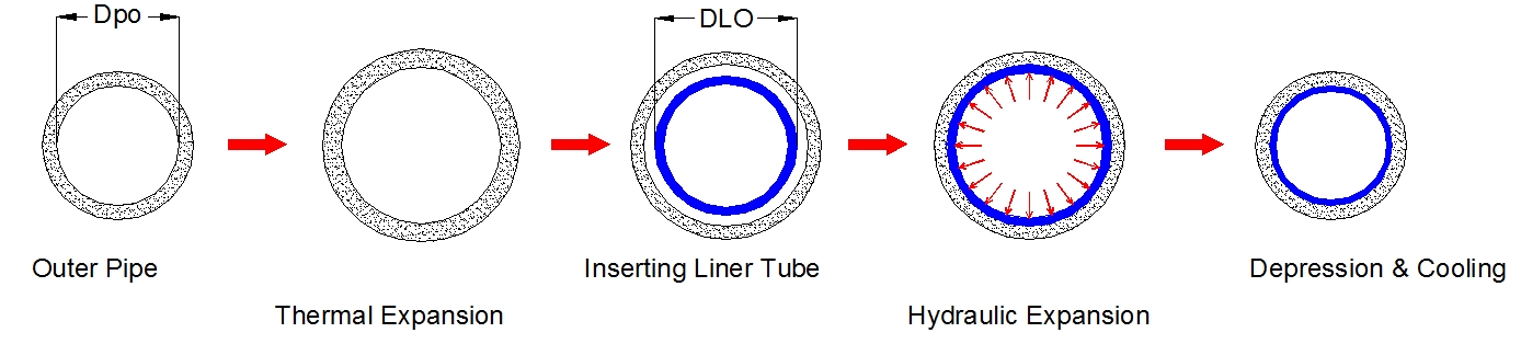
4.7.3 Thermo-Hydraulic Fit Method
CRA Lined pipe can also be manufactured using the ‘’thermo-hydraulic fit method’’ as shown in Figure 4.10, “Thermo-hydraulic Fit Method For Tightly Fitted Lined Pipe”, which is, in principle, a combination of the ‘’thermal shrink-fit method’’ and ‘’hydraulic expansion method’’. This technique allows producing economically long lined pipe with high fit-in stress. The principle and the procedure of this method is as follows : Into an outer pipe which has been heated and thermally expanded, a liner tube is inserted and expanded by hydraulic pressure. After removing the pressure and heat in the outer pipe, the tight fitted lined pipe (TFP) is obtained. By this method, the accuracy of fitting is achieved by plastic expansion of the liner tube and the desired fit-in stress is achieved by thermal shrinkage of the outer pipe. By the use of this manufacturing procedure, many problem inherent to usual lined pipes, such as implosion, stress corrosion cracking and general corrosion, have been solved.
4.8 High Density Polyethylene Liner
Lined pipelines provide a cost effective alternative to conventional corrosion mitigation methods such as chemical injection, extensive de-oxygenation, use of corrosion resistant alloys (CRA) and the inclusion of sacrificial corrosion allowances in the pipeline wall thickness.
Plastic lined pipelines consist of a carbon steel pipe internally lined with a close fitting polymer pipe. This plastic pipe (known as a liner) acts as a barrier between the transported fluid and the steel pipe. Conventionally the liner material used has been either medium density or high density polyethylene (MDPE or HDPE).
Internal lining of carbon steel pipelines has been successfully used onshore in both hydrocarbon and water injection service and offshore in water injection pipelines in place of existing corrosion protection methods. When compared to carbon steel pipelines, operational costs can be reduced as no corrosion inhibitor is required and carbon steel costs can be decreased, as there is no requirement for an internal corrosion allowance, although cost of lining must be factored in.
The most significant advantage however, is that plastic lined carbon steel pipelines are less expensive than pipelines fabricated from corrosion resistant alloys.
Conventional polymeric liners have been shown to be susceptible to failure when transporting hydrocarbons and other fluids with gaseous components. Permeation of these components through the liner can result in pockets of gas becoming trapped between the liner and the host pipe which, on depressurisation of the bore, may expand and partially or completely collapse the liner.
Traditionally, onshore, this has been achieved by installing vents at regular intervals and evacuating the gases periodically. This venting system has to date been considered impractical for subsea applications. However, Technip has completed a three year development and testing programme based on a grooved liner system which incorporates a reliable venting mechanism, and which is designed to be installed offshore by the reel lay method.
The plastic lined flowline is a competitor to 13% Chromium pipes and Duplex pipes. The liner also is beneficial for applications with sour service fatigue problems such as steel catenary risers (SCRs).
The perforated liner concept is a method of preventing collapse by drilling holes in the liner at regular spacing, thus allowing the pipeline liner annulus to remain pressure balanced with the bore. By careful selection of the diameter and spacing of the holes, the corrosion prevention properties of the liner can be maintained.
The plastic lined pipeline for hydrocarbon transport (PLHT) system is only suitable for reeling applications at present. Further development and economic analysis is required prior to establishing its viability for S or J-lay installation.
The PLHT system is suitable for the following applications:
Production and produced water -injection containing entrained gases;
Moderate temperature applications (60 - 70ºC operating temperature – pH dependent)
Corrosive environments (H2S and CO2)
The benefit of the PLHT system is that it is a cost effective alternative to Duplex or 13% Cr pipe. The liner provides an effective corrosion barrier which negates the need for costly corrosion resistant alloys or expensive chemical inhibition programmes.
The liner also insulates the pipe which in some situations will decrease the external coating required, whilst achieving the same OHTC value.
The PLHT system increases the specific gravity of the system due to the liner’s presence. In some situations this may negate the requirement of the system to be trenched and backfilled.
The presence of the liner between the hydrocarbon and the steel pipe leads to a decrease in the steel temperature. This decrease in temperature reduces axial expansion and in turn may equate in the pipe not requiring mechanical restraint, i.e. trenching and backfilling.
In situations where the liner has reduced external coating requirements there will be situations where vessel trips could be decreased.
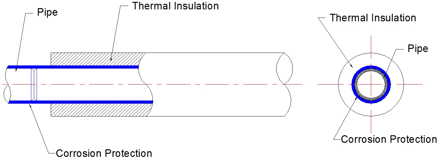
4.9 Wet Insulated Rigid Pipe
The design of a deepwater wet insulated rigid pipeline is based on the following considerations:
To be safely placed on seabed during deep water installations
To have an operating temperature up to 120°C
To be able to fit for all the different laying methods, and especially reeling puts stringent flexibility requirements to the pipe as external coating could be exposed to more than 2% elongation when reel-laid.
From the above, a typical wet insulated system consists of (see Figure 4.12, “Figure 4.9: Composition of wet insulated rigid line”):
Thick and rigid pipe made in carbon-manganese steel, 13% Cr steel, clad steel pipe or duplex stainless steel
Corrosion protection on the steel surface made in fusion bonded epoxy instead of coal tar due to the outstanding properties at elevated temperatures. Anti-corrosion coating of a pipe consists to spray epoxy powder onto pipe pre-heated at about 232°C
Insulation material made of syntactic foam (polyurethane or polyethylene)
External coating (polypropylene) to ensure mechanical protection (towards impacts) and sealing (towards the sea water) of foam shells which, when exposed to external hydrostatic pressure, could be filled with water in a longer period of time
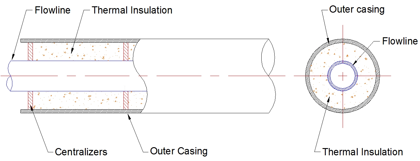
4.10 Pipe in Pipe System
A typical pipe in pipe system for reel lay (see Figure 4.13, “Figure 4.9: Typical pipe in pipe system”) consists of a casing pipe housing an insulated wrap flowline pipe, concentrically positioned in the carrier pipe by means of spacer blocks placed every 2.5m on the production flowline. Insulation material is strapped and attached onto the production flowline pipe using galvanic steel, tape or band wire. The assembly of pipe in pipe consists to pull the production pipe into the outer casing pipe in one continuous length while securing spacer blocks and insulation material on production flowline pipe.
A basic pipe in pipe concept applicable for other methods of installation (S-lay, J-lay, Towing) comprises of an inner product carrying pipe inside an outer sleeve pipe. Variations occur when the specific detail of pipe materials, bulkhead configuration, insulation system, field joints or method of fabrication change.
The sleeve (or outer) pipe has a multipurpose role in the design of a pipe in pipe system. Keeping the insulating material dry is one of the most basic requirements when designing and installing an insulated subsea pipeline. An obvious solution is to surround the insulation with an external waterproof sleeve (wet insulated system). The use of a sleeve will also protect the insulation material from mechanical damage during installation and service. It reduces the overall thermal loads within the system and can reduce the installation stresses experienced by the system.
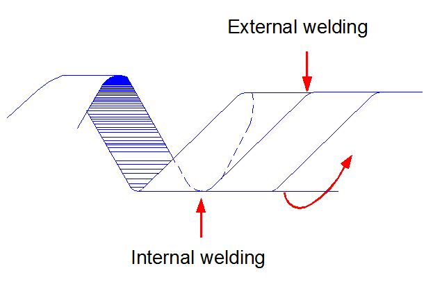
Load transfer can occur between product carrier pipe and sleeve pipe, which results in reduced thermal expansion. This is typically achieved by use of a welded connection (bulkhead) between inner and outer pipe that also provides a high integrity water stop (see Figure 4.14, “Figure 4.10.2: Bulkhead assembled between 8-in oil line and 14-in sleeve”).
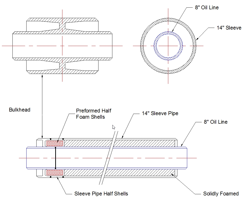
During the assembly of the pipe in pipe system, the flowline joints are welded together and insulation field joints are applied to fill the gaps at the welds. The sleeve pipes are joined by fillet welding half-shell steel sleeves over the insulation field joints. Preformed half foam shells are top surface fire resistant to prevent from arc burn during welding operation. Preheating may be required for TIG orbital welding process but there is no post weld heating for welded joints of C-Mn steel pipe having nominal wall thickness less than 49mm.
The main drawbacks with the use of bulkheads in the pipe in pipe system are numerous cool points along the flowline at every bulkhead locations.
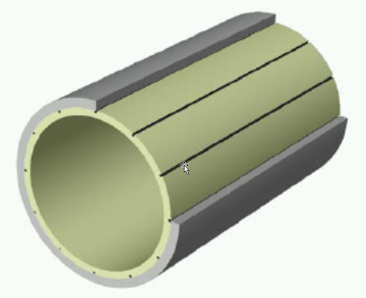
4.11 Pipeline Bundle System
This configuration is defined as having multiple flowlines, hydraulic control and service lines, and electrical umbilicals encased or integrated in a single carrier pipe or casing (see Figure 4.15, “Figure 4.10.2: Pipeline in bundle configuration”). As required electrical or circulating fluid heating lines could be integrated to reduce the risk of hydrate and wax plug formation when production lines are shut down or to heat up the production lines before start up.
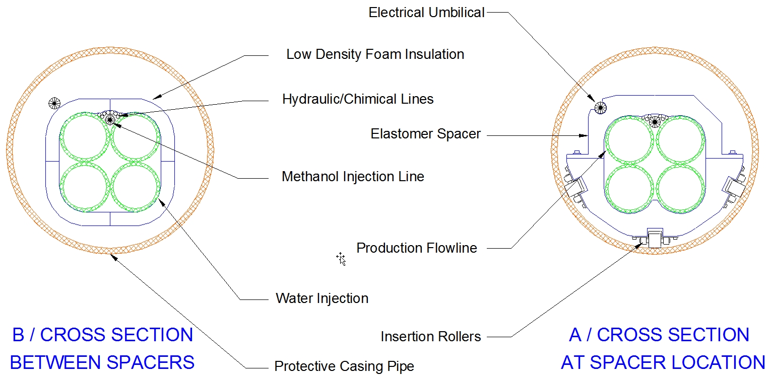
In the deepwater pipeline bundle configuration, all flowlines are wrapped in two half shells of moulded low density, open-cell polyurethane foam, approximately 2-in thick. This isolates the warm space near the flowlines from the cool annular space in the casing. Hard polyurethane spacers are used to secure all flowlines and umbilicals. Rollers wheels on the spacers facilitate flowline bundle pull-in into the outer casing. There are no intermediate bulkheads isolating the annular space of the casing. The entire annular space is permanently pressurised with nitrogen, in order to maintain zero differential pressure across the casing wall at the deepwater end. This allows the casing to resist collapse while minimising the required casing wall thickness and bundle diameter. An unusual aspect of the bundle is the high casing diameter to thickness (D/t) ratios, which approach 100 for deepwater pipeline configuration.
The fabrication of the bundle started with the welding of carrier pipe followed by the pull-in of the internal components as the assembling proceeds. The bundle is fabricated onshore using a relatively inexpensive fabrication spread (compared to an offshore lay vessel), and then is towed to location using a construction spread that may consists of two high bollard pull tugs and a survey vessel.
The design of a pipeline bundle to be installed by tow method is considerably more complex than that of a normal submarine pipeline. The design embraces fabrication, installation and operational requirement, and proceeds from the inner pipe outwards to the carrier pipe with iterations of design where necessary.
Typical design considerations are as follows:
The inner pipeline material and wall thickness are based on normal operating and design conditions and maximum allowable stress, as well as accounting for axial restraint imposed on the pipe by carrier pipe and seabed friction
Minimum thickness of PUF insulation is calculated on the allowable temperature drop for a given duration
Nearest standard pipe-sizes and wall-thickness is chosen for the carrier pipe to accommodate the required amount of lines and insulated material
The carrier pipe is not subjected to direct effects of product flow, but is stressed by heat transfer through the PUF and by pressure/temperature effects from the inner pipe via the bulkheads placed at defined distance
The carrier pipe is designed to provide adequate buoyancy during towing and requires sufficient wall-thickness to withstand beach-pull, break-out load and towing loads
The bundle’s on bottom stability
The whole bundle is checked to ensure it is capable of withstanding dynamic loads occurring during launch, tow and installation
For ultra deep water application (i.e. beyond 1500m WD), there are practical difficulties in the design of the carrier pipe for the tow operation due to:
Carrier pipe D/t ratio optimisation with regard to nitrogen pressure and weight
Bundle overall net submerged weight for tow operation
| Note On Asgard project, the annulus is filled with inhibited water at ambient pressure after the tow operation. |
In this case, the industry is proposing a wet-insulated bundle based on "syntactic foam" with the adequate thickness (e.g. typically in 30" to 32" diameter shell) to provide:
Sufficient buoyancy during towing
Minimum thickness insulation material
A thinner carrier pipe (e.g. 6mm – 10mm wall thickness) can be retained for the purpose of "wears" during beach-pull (or bottom-tow method), while providing a mechanical containant.
Under external hydrostatic pressure, this carrier pipe would collapse in a non controlled manner onto the syntactic foam which is pressure resistant.
On completion of towing operation and position confirmed by ROV, the bundle will be connected in diverless mode to the others subsea systems and equipments.


