
3 deepwater riser design methodology
3.1 General
The different risers systems are composed of flexible pipes, steel pipes, or a combination of both technologies. Each of these riser systems has its own design codes and standards, which are further presented in the following sections.
![[Tip]](tip.png) | Tip Click these links below for access to 3D resources: |
3.2 Steel riser systems
3.2.1 Design methodology
SCR design methodology is presented in the following flowchart Figure 3.1, “Steel catenary riser design flow chart”.

The design checks related to the different design phases of a steel riser system are described in the following sections.
3.2.2 Selection of the riser section
A starting point of the design process is the definition of the riser internal diameter as a function of the fluid characteristics and of the required flow rate. The wall thickness is initially defined to guarantee:
Containment of the maximum internal pressure (bursting)
Adequate strength against local buckling due to external hydrostatic over-pressure (if any) axial force and bending moments
Sufficient strength to resist propagating buckling in absence of buckle arrestors
Adequate apparent weight for the on-bottom stability against lateral current loads.
Consideration for corrosion due to internal fluid and to the sea environment shall be performed to identify the actual material characteristics, the required corrosion allowance and the specifications for external coatings (if any).
The assessment of the minimum wall thickness for the riser components can be based on the following codes and standards: API RP 1111, API RP 2RD and ASME B31.4/B31.8, or the DNV codes (Section 1.2).
3.2.3 Selection of the basic configuration (static analysis)
Static analysis is the fundamental step for preliminary definition of the riser configuration. The design water depth, the maximum static offsets and the heave motions imposed by the floater allow the designer to select the most suitable geometry from the possible alternatives. The definition of the riser total length and the amount of buoyancy (if any) are the next step to achieve a well-balanced initial configuration. Such configuration results into a compromise between the top end tension, the peak combined stresses arising in the touch down point (TDP) or in the bent areas (e.g. arch) and the maximum angle variations at the riser terminations. An adequate margin against the expected dynamic amplification must be accounted for starting from this phase, in order to consider realistic data (e.g. dynamic amplification factor, typically within 1.2-1.3 range, is used to determine the dynamic tensions from the static results).
3.2.4 Dynamic analysis – extreme conditions
The mooring system analysis, using numerical or physical models with a statistical representation of the environmental conditions, allows the prediction of the extreme offsets for the floating production system. These values shall be determined for intact or damaged mooring conditions, considering both parallel (current, waves and wind collinear) and transverse weather (current, waves and wind non-collinear) extreme conditions. The transfer functions for the six components of the vessel motion (Response Amplitude Operators or RAOs) in the wave frequency range are usually provided. The top end of the riser is generally subjected to the direct action of waves and current in conjunction with the imposed motion defined by the combination of RAOs with the considered Sea State. The dynamic analysis of the riser is generally based on a time domain approach with non-linear structural and loading models, using both regular and irregular spectral wave conditions.
The main parameters subjected to checks are:
Effective tensions
Bending moments and combined stresses along the entire riser length
Angular excursions and reactions forces at the top end
Transverse riser motions
Bending moments and potential compression at the TDP
Particular attention has to be paid, under severe storm conditions, to avoid excessive axial compression in the lower part of the riser (close to the TDP), which can lead to uncontrolled deflected shape and involve high bending radius and hence buckling of the pipe.
3.2.5 VIV analysis
The need for VIV suppressors should be investigated with respect to VIV effects induced as part of the riser fatigue damage. Should excessive motions be expected, effective suppressors will be selected and applied to the required riser length. Numerical model of the problem is required in order to evaluate the envisaged solutions.
A simplified assessment of VIV is proposed in DNV-OS-F201. This simplified estimate of the induced fatigue damage is computed conservatively by assuming 2D sheared current profiles to apply on the riser (e.g. unidirectional with a magnitude that varies with distance below the sea level).
A lot of developments have been identified in this particular area. Softwares, such as SHEAR7 and VIVA by MIT, OrcaVIV by Orcina are now potentially suitable for handling VIV issues.
3.2.6 Fatigue analysis
The total fatigue damage is assumed being generated by the combined action of the following contributions:
Mean motions of the vessel caused by the sequence of storms foreseen in the long-term distribution
Slow-drift motions of the vessel inside each storm event
Wave-frequency motions of the vessel and hydrodynamic loads applied directly to the riser for each of the above events
Vortex induced vibrations (VIV) effects in riser length exposed to high current profiles (e.g. first few 100 meters below sea surface level)
Installation operations
The admissible fatigue life is assumed to be equal to e.g. 10 times the design life for the entire pipe length. Suitable criteria will be defined to couple a particular environmental condition (wave and current) with the corresponding vessel offset. A time-domain approach will be followed to describe the dynamic response of the riser generated by the representative sea-states of the long-term distribution. The total fatigue damage is then evaluated by means of a suitable procedure that shall be aligned with the solution approach, considering a reference S-N (Stress range – Number of cycles to failure) curve like HSE, API X (in RP 2A), DOE or DNV OS C203 curves and the Palmgren-Miner law for summing the partial contributions.
3.2.7 Temporary conditions
Temporary conditions are generally associated with the life phases of the system before operation. They include:
Construction: On-shore or off-shore assembly and handling of the riser
Transportation: Using surface, immersed or controlled-depth towing methods
Installation: Directly operated by the towing vessels or by the laying vessels.
These phases, together with potentially disconnection and retrieval operations, must be considered within the analysis methodology in order that maximum riser responses in transient static and dynamic conditions are captured. The reference meteocean conditions are identified on the basis of the estimated duration of each operation and of the period of the year selected for the activity.
3.3 Flexible risers
The flexible riser technology is presented in Section 5.2, and the main design aspects, which need to be addressed in deep water flexible pipe design, are:
3.3.1 Hydrostatic collapse at design water depth (pipe empty condition)
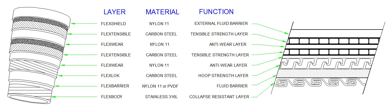
In conventional flexible pipe, the internal carcass has been designed to provide all of the collapse resistance to the flexible structure. The pipe must be designed to have sufficient collapse resistance with the outer sheath damaged. In this case, the external hydrostatic pressure penetrates the structural layers (pressure and tensile armours) and bears against the fluid barrier.
For deepwater application, a solution to provide additional collapse resistance without adding substantial weight will consist in modifying the pipe structure such that the external hydrostatic will bear outside the pressure armour. Thus both the pressure armour and the carcass will provide internal ring stiffness increasing the collapse resistance.
A further improvement in the collapse resistance for larger diameter and deeper water requires increased ring stiffness of the internal carcass and/or pressure armour.
3.3.2 Axial compression of the pipe structure due to the reverse end cap load
The axial compressive stiffness of conventional flexible pipe is an order of magnitude lower than the tensile stiffness. When a flexible pipe is subject to axial compression, the tensile armour layers expand radially (i.e. increase of the diameter under compression known as Poisson's effect), with resistance to expansion provided by the helical wrapped tape over the tensile armour and the external sheath itself. The reverse end cap load in deep water is substantial. For example, a 6" ID empty pipe at a water depth of 2000 meters is subject to more than 80 tonnes reversed end cap load.
There are three potential modes of failure of the flexible pipe resulting from the reverse end cap load:
Buckling of the tensile armour wires themselves
Rearrangement of the tensile armour layers resulting from the radial expansion
Failure of the outer sheath
If the flexible pipe is not torsionally balanced under axial compression, or has residual torque due to the manufacturing, reeling or installation processes, then the resulting twist can increase the radial expansion of either the outer or the inner tensile armour layer. This would increase the potential for these failure modes to occur. Thus torsion loading must also be considered in evaluating the resistance of a flexible pipe structure to reverse end cap loads.
3.3.3 High tension load in operation of dynamic risers due to pipe weight and dynamic amplification
In order to reduce the tension loads on flexible pipe for deep-water applications, a system approach can be applied. Different flexible pipe structures are used with a mid-line connection between the flexible pipes. The top section is designed for higher tensile capacity and the lower section is designed for high collapse resistance. This approach saves substantial weight over making the entire pipe designed for both the required collapse resistance and top tension capacity. The high tension capacity pipe can be made with carbon fibre / composite tensile armour to result in further weight reduction.
The estimated weight saving versus steel armoured pipe by using a combination of steel structures composed of high tensile capacity top section and high collapse resistance bottom section is 25%, and 50% for high tensile capacity top section with composite armour and high collapse resistance bottom section with steel armour
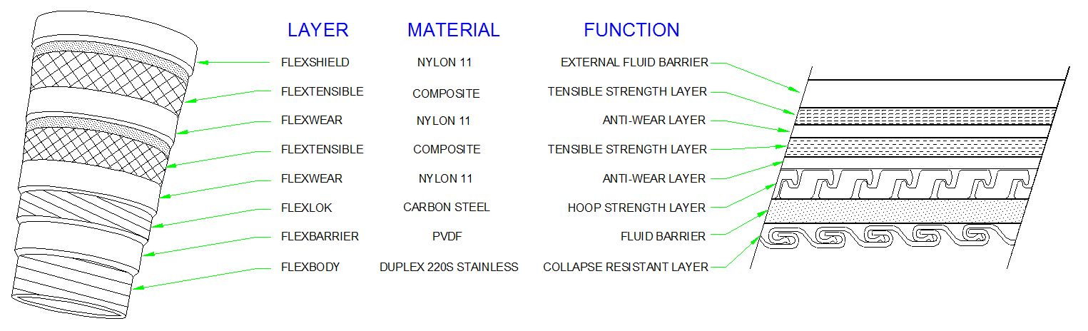
Figure 3.2, “Non-bonded flexible pipe structure” and Figure 3.3, “Non bonded flexible pipe structure using composite armour material” present the pipe design and capabilities of the composite armour relative to the steel material currently being used. In addition to weight reduction, the composite armour offers the advantage of being essentially inert to corrosion, hydrogen induced cracking and sulphide stress cracking, all potential mechanisms for reducing the service life of a flexible pipe.
The following table provides mechanical properties comparison between steel and composite materials:
Table 3.1 - – Mechanical properties comparison
Steel | Carbon Fibre Composite | |
Configuration | Cold rolled/Heat treated Rectangular cross section 3 – 6 mm thick Mechanically performed to helical structure | Thermoplastic/Carbon fibre matrix Rectangular cross section 1 – 2 mm thick 2 – 4 layers Helically wrapped |
Strength | 759 MPa | 1,255 MPa |
Modulus | 207 GPa | 80.7 GPa |
Elongation | 11% or higher | 1.4 % |
Density | 7.85g/cc | 1.48g/cc |
3.3.4 Installation Loads
The flexible pipe structure must be designed to withstand the following installation loading conditions:
Radial compression with tension to simulate loading condition at tensioner
External hydrostatic pressure, zero internal pressure with and without bending and torsion
Tension and radial compression loads on external sheath
The pipe structure is checked by stress analysis to verify that it can withstand these combined loading conditions. Where necessary, the pipe layer dimensions or materials are modified to assure that the loading is within the allowable utilisation factors prescribed in API specification 17J.
3.3.5 Depth Limitation
The following figure sets the flexible pipe water depth limitations (typical), and further details on flexible pipe technologies and applications are provided in document Ref. [34].
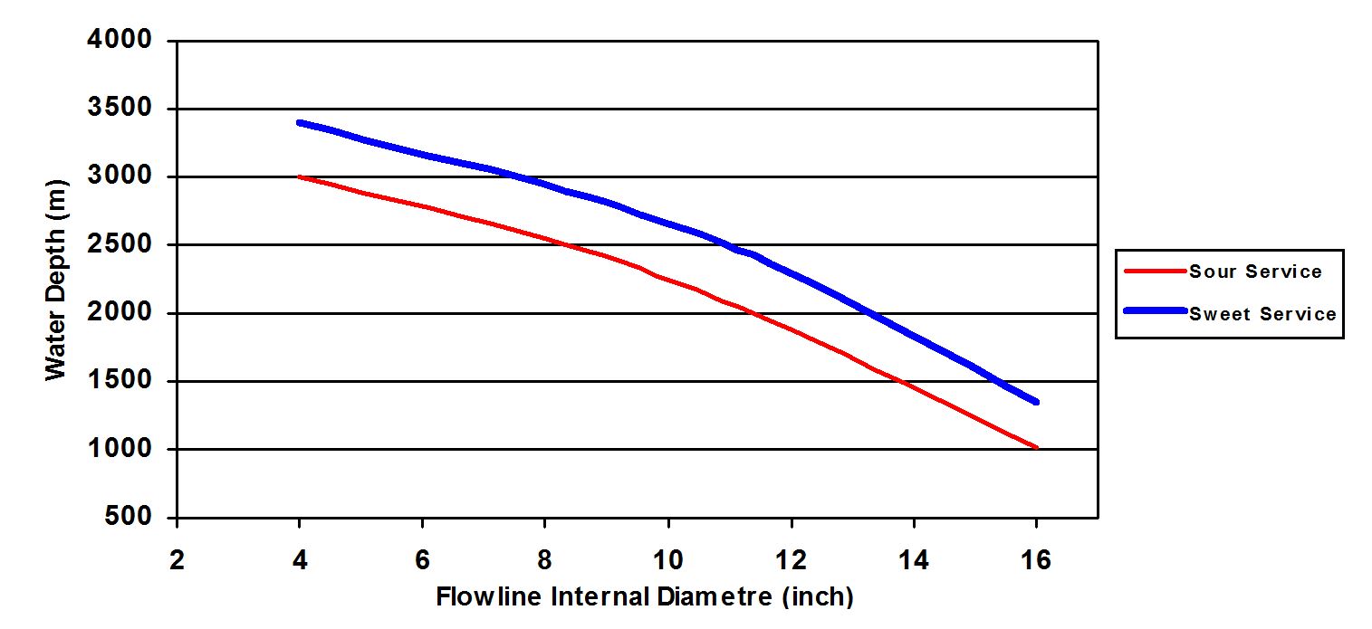
![[Note]](note.png) | Note Maximum water depth based on the following basis,
|
3.4 Hybrid riser Systems
A typical analysis method of a hybrid riser system (see descriptions in Section 5.4) is presented hereafter.
3.4.1 Global Dynamic Analysis
The analysis is mainly concerned with:
System configuration based on water depth, stand-off distance to FPS, flexible jumper length, clashing issue, rigid base jumper design, etc.
Hydrodynamic loads induced by extreme sea (storm) conditions combined with current profiles.
FPS 1st & 2nd order wave motions and slow drift offsets (to include mooring line failure) coupling to the hybrid riser system by way of the flexible jumpers.
Fatigue damages due to (a) wave induced excitations, (b) current profiles and vortex induced vibration (VIV), (c) buoyancy can vortex induced motion (VIM) and during the initial installation phase.
Installation analysis of the hybrid riser systems, e.g. ‘big’ buoy handling and deployment, rigid pipe lay operation, flexible jumper tie-ins and lay-away, riser base jumper
3.4.2 Mechanical Sizing
For hybrid riser tower (Section ), the mechanical sizing of the Flowlines and the central core (or stem) pipe is based on burst, hydrostatic collapse and effective tension analysis. A local buckling analysis will be performed based on the global dynamic results in order to check the initial wall thickness evaluation.
The lines are not designed against the buckle propagation criterion because low bending radii are not expected during installation and production phases. Designing the lines to meet the buckle propagation requirement would be over-conservative and would involve higher steel weight, a bigger subsea buoy and therefore higher drag loads on the riser system.
For a hybrid 'S' riser (Section ), steel catenary risers are designed as in Section Section 3.2.2, “Selection of the riser section”. This kind of system also requires the sizing of the tethers. In case of steel tethers, the API-RP-2SK provides the design criteria for both intact and one damaged tether conditions. No compression must occur within the tethers during the field life which would induce detrimental effect by snatch loads. For the composite rope (e.g. polyester) alternative, the design criteria relative to the allowable minimum tether tension, to the maximum tension limits and fatigue given in API RP 2SM must be verified.
3.4.3 Insulation Sizing
The different steel risers can be independently insulated similarly to the SCR system.
In a riser tower concept, syntactic foam in modular forms are used for the purpose of added buoyancy of the riser through its entire length but could also participate to the riser bundle insulation. The minimum foam thickness is given by manufacturing process, mechanical resistance and insulation considerations. The external diameter of the riser tower and the foam modules is governed by:
riser tower section arrangement (i.e. the number, the diameter and the repartition of the Flowline risers around the central core pipe)
Minimum thickness of foam
Required buoyancy of the tower, especially for tow stability considerations.
3.4.4 Subsea Buoy Sizing
The subsea buoy’s net uplift force is dictated by:
Static equilibrium of the hybrid riser system in production mode with the required tension provision in order to avoid any dynamic compression of the central member in case of a riser tower and in the tethers in case of a hybrid 'S' riser. The dynamic analysis will verify that no compression occurs.
Eigen period analysis, as the first natural period of the hybrid riser system is mainly governed by the subsea buoy tension.
3.4.5 Eigen - Mode Analysis
The Eigen mode analysis is required to prevent the hydrodynamic coupling between the riser system and the FPS 1st and 2nd order motions.
The analysis will consider the 1st and 2nd Eigen periods of the hybrid riser system. In general, such natural periods would be expected to be:
Pendulum mode, parallel and perpendicular to the FPS longitudinal axis
Bending mode (2nd Eigen period associated with the first bending mode)
The dynamic response can be of two different natures: (1) inertial response governed mainly by the excitation period and (2) resonant response at a natural period of the system, governed by the existing damping rate.
The pendulum resonance mode (i.e. low frequency resonance) can be prevented by a proper hydrodynamic design of (1) subsea buoy tension and (2) flexible jumper configuration, to obtain a pendulum frequency higher than the FPS slow drift frequency but lower than the subsea buoy vortex shedding frequency.
The riser tower bending mode can be excited in the high frequency range, which can varied from high frequency (flexible riser VIV) to the wave frequency range (e.g. FPS 1st order motion, riser tower VIV).
For the subsea buoy, the vortex shedding frequency falls in the low frequency range.
3.4.6 Hybrid riser System Response Optimisation
Optimisation of a hybrid riser system response during the design phase is achieved by adjusting the following parameters:
Volume and location of distributed buoyancy
Buoyancy can up-thrust
Offset distance of riser base from FPS
Flexible jumper length and submerged weight
Depth of buoyancy can to avoid high currents and wave impact
3.5 Design software for riser systems
Time domain non-linear dynamic analysis:
Finite Element, Frequency domain, Time domain non-linear analysis:
ABAQUS
ANSYS
COSMOS (developed by Structural Research & Analysis Corp)
Vortex Induced Vibration and Vortex Induced Motion analysis:
Shear 7 (developed by MIT)
VIVA (developed by DTCL ltd)
OrcaVIV (partial CFD method developed by Orcina)
Flexcom/Modes 3D (developed by MCS International)


