
8 Vortex induced vibrations
8.1 General
The vortex vibrations are induced by a fluid flow acting on cylinder elements (i.e. vibrations due to vortices, see Section 7.2, “Electrical heating”) and forcing them to vibrate by exciting their closest eigen mode (i.e. mode shape associated to natural frequencies of the pipe closest to the vortices oscillation frequency).
The rigid pipe riser systems are mainly associated to the VIV problem. The high inertia value of the rigid pipes involves high natural frequencies, which correspond to the VIV excitation periods. But even risers made of flexible pipe, which have large structural damping, can experience VIV, although the consequences are quite minimal and thus are not a real concern.
VIV generally does not induce high stresses in the rigid pipe Riser, but it is damageable to the system as it reduces its fatigue life by inducing high cyclic loads.
8.2 VIV prediction
The VIV prediction is a complex subject, especially for deepwater riser systems. This vibrating phenomenon can be basically described as follows:
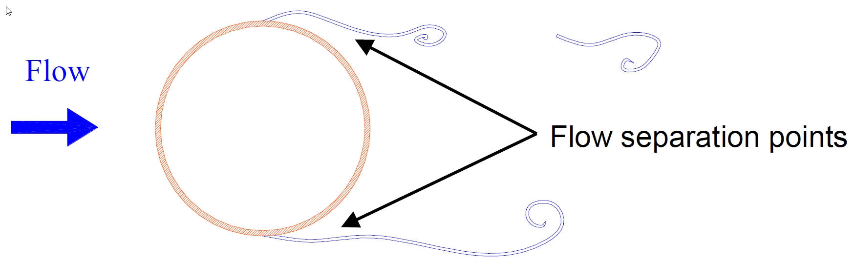
The riser, immersed in a fluid flow, creates vortices; the two separation points (see Figure 8.1, “Fluid flow sketch”) oscillate on the riser sides, thus creating forces that oscillate at the vortex apparition frequency. There are two types of oscillation: (1) oscillation in-line with the velocity motion and (2) oscillation perpendicular (cross flow) to the velocity vector.
This vibrating phenomenon becomes critical when the cross flow force frequency is relatively close to one natural period of the riser. This phenomenon called “lock-in” occurs (i.e. pipe oscillates at its natural frequency which is closest to the excitation induced by the vortices) which can result in serious damage by reducing the fatigue life of the system.
Predicting VIV and estimating response amplitude and frequencies are key issues when determining the fatigue life of a riser system.
The difficulty in predicting VIV occurrence and effects is due to:
Uncertainties about the environmental conditions that will be encountered by the riser system, especially current profiles (magnitude and shape variation with depth).
The inability to fully understand and model the fluid-structure interaction.
Lack of full scale response data; the VIV prediction formulae are based on empirical coefficients which are not well defined as they were determined for some particular cases and often in laboratory conditions. These empirical coefficients are highly dependent on several parameters such as the riser system data (diameter, length, shape of the riser, marine growth, etc.) and the environmental conditions (i.e. current profile).
Multiple mode VIV that may occur due to the current profile variations with depth, several natural bending modes may be simultaneously excited into VIV (i.e. the riser experienced different frequencies of excitation with depth).
The presence of adjacent riser, which modifies the fluid flow and creates shedding.
Some verification rules and methods are recommended by classification societies or institutes supplying with regulations and codes (such as DnV, API, etc.). These methods are based on simplified formulae, which allows quick verifications and estimations but are generally conservative.
Programs are also available to help in VIV occurrence and effect prediction (see section Section 3.5, “Design software for riser systems” ). The most widely used is the MIT program SHEAR7. Indeed, VIV excitation and the resulting damage and displacement can be calculated using SHEAR7 program. SHEAR7 predicts cross flow VIV response in sheared flow based on modal superposition. A power balance procedure is used to determine the VIV response of the riser by balancing the power input in regions subject to VIV against the power output in regions providing hydrodynamic damping.
SHEAR7 is used for predicting the VIV fatigue damage rate for each of the current events.
The total VIV fatigue damage on a riser can be obtained by summing the damages from each current bin (yearly current and storm current profiles).
SHEAR7 is capable of performing only simple modal analysis but has the capability of importing more accurate modal analysis results generated by another computer program. Modal analysis can be therefore performed in MODES software at the riser neutral configuration (still water static configuration of the riser without current effects).
8.3 Vortex suppression devices
If potential VIV effects are detected during the engineering phase of a riser system, one of the two following solutions may be used:
Either redesign the riser by modifying the tension, changing its mass or designing another configuration. This solution is generally costly and may have repercussions on the production floater.
Or add vortex suppression devices.
The primary function of a VIV suppression system is to mitigate the effects on the SCRs of vortex shedding, which causes VIV. VIV suppression devices aid in reducing or nearly eliminating the effects of VIV and thus increasing the SCR fatigue life.
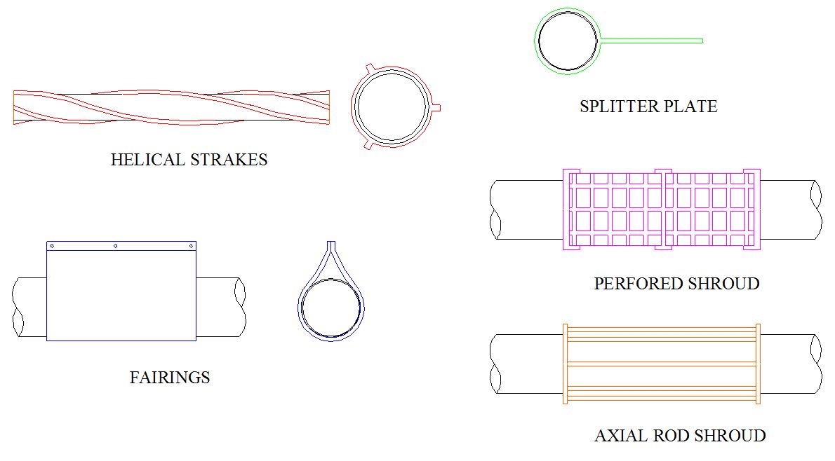
The main VIV suppression devices (Figure 8.2, “Main VIV suppression devices”) are:
Helical strakes
Fairings
Perforated or axial rod shrouds
Splitter plates
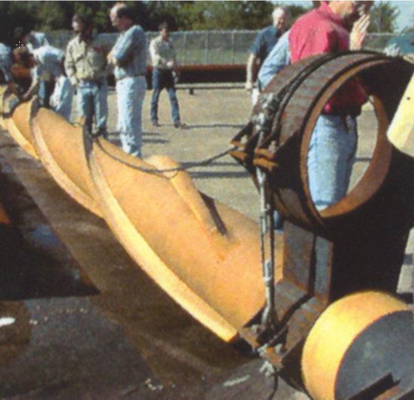
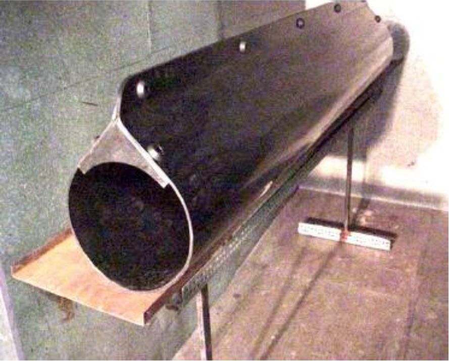
The most popular devices are the helical strakes (Figure 8.3, “VIV helical strakes”) and the fairings (Figure 8.4, “VIV fairings”). Weathervaning fairings are for example used in the Gulf of Mexico on the Shell Mars TLP risers, while helical strakes equipped the export steel catenary risers of Auger.
Experiments on helical strakes have shown that:
Strake height has a large impact on suppression efficiency, while strake pitch is not as influential
The coverage length has a large effect on suppression efficiency. For certain currents, suppression can have only a local effect and thus more strakes may be needed to achieve the desired level of suppression along the entire tubular.
The efficiency of strakes decreases and the drag loads increase when an upstream tubular is present.
Both strakes and fairings can dramatically reduce VIV fatigue damage (by over 80%) but introduce intrinsic disadvantages:
Both complicate the installation phases as the equipped riser system is difficult to handle.
Strakes increase the riser drag, which is detrimental to the riser behaviour, and require a continuous coverage of the VIV sensitive length.
These systems increase the risers costs, helical strakes being more expensive than fairings.
Fairings can reduce drag loads and only require a partial coverage of the critical length of the riser, but they need to rotate with current direction, which is a great disadvantage for long-life utilisation, as efficient anti-fouling devices are required to avoid their gripping by marine growth.
Strakes can induce excessive drag loading if filled with time by shells such on Mars and Bonga risers


