
7 Heating techniques
7.1 General
Heating technique, considered as active subsea insulation method, is viewed as a key technology for flow assurance as the industry moves into increasingly deep waters. This will help to reduce the risk of hydrates and wax plug formation when production lines are shut down while at the same time reducing the risk of environmental contamination through leakage of chemicals currently injected into the lines as a preventive measure.
The heating techniques may be designed for the following purposes:
To maintain steady state pipe temperature above the hydrate formation temperature (typically 15-25°C) after planned or non-planned shutdowns. The objective is to start the system prior to hydrate formation
Heating of the pipe, which have been cooled down to the ambient seawater temperature. This situation might be valid after the unlikely situations of either a very long major electric power system shut-down, > 10 hours, or after a simultaneous process shut-down and heating system failure
The system could also be used to maintain the required temperature at low production rates.
The rating of a heating system is dependent on many factors. These might be material or operational parameters, or design criteria.
The following parameters are essential for the design of the heating system:
7.1.1 Pipeline
Material/composition thermal data
Dimensions: diameter/thickness
riser insulation: dimensions (thickness), thermal conductivity (with corresponding U-value and heat capacity)
Thermal data and dimensions of protection on the riser section resting on the seabed (surrounding/seabed, including depth of gravel, rock dumping, etc.)
Thermal properties of the pipe content in different operation modes
Geometry/length of riser
7.1.2 Design criteria
Temperature of seawater
Sea depth
Steady state temperature
Required heating time
Required melting time
At present, the main active heating techniques proposed by manufacturers to heat up risers are listed below:
Electrical heating applicable to thermally insulated rigid steel risers. It can be applied for continuous operation, shutdown and restarts.
Hot fluid circulation heating applicable to flexible and rigid steel risers. This is applied in a bundle design which contains production lines and heating lines together. This technique can also be applied for continuous operation, shutdown and restarts.
Hot oil circulation: Hot dead oil is circulated through a flow loop in the production flow path to warrm flowlines and risers prior to restarting wells or during a shutdown until the system is restarted. Hot fluid could be circulated inside steel PIP annulus. A fluid other than dead oil can also be used.
7.2 Electrical heating
The following techniques based on electric heating may be used:
- Electric heating cables (indirect heating): This employs electrical cables as heating elements that are directly attached to the outside surface of the Flowline. The current passed in the cables heats the cables, and the heat is transferred to the Flowline.
- Electromagnetic induction heating (indirect heating): An electrically insulated cable in a steel tube is fixed to the Flowline surface. The tube and cable are electrically connected together at the far end. An AC power source is connected between the tube and the cable at the other end. Current flows through the cable and returns through the tube. Due to the magnetic properties of the steel tube, the cable current induces large currents on the inner surface of the tube. The heat generated by the tube then transfers to the Flowline by thermal conduction.
- Direct electric heating: The Flowline is used as an electrical conductor. A large electric current is passed along the walls of the Flowline. Owing to the electrical resistance of the pipe, power, is dissipated within the Flowline walls causing direct heating.
Refer to chapter “Heating techniques” in document for further information on electrical heating systems.
In all three methods, electric heat is used to maintain or raise the pipe temperature above the critical value for hydrate (typically 15-25°C) or wax formation (typically 20-40°C).
The TECHNIP-FMC group has developed a number of pipeline and riser concepts with high efficiency passive and active insulation in order to meet the deepwater market requirements. The reelable heated PIP (HPIP) (equivalent product developed by SS7 and called ETHPIP) and the IPB are two of these concepts.
The HPIP combines the high efficiency of the passive insulation of a standard PIP and active heating using a number of trace heating copper core cables, positioned onto the Flowline, below the insulation, in order to maximize the heating efficiency of the system.
The IPB (see section Section 5.2, “Flexible Riser Systems” ) also incorporate an active heating system.
Some projects using electrical heating are presented in the following Table 7.1, “- Project using electrical heating”.
Table 7.1 - - Project using electrical heating
Operator / Project | Line Diameter / Length | WD (m) | Year of installation | Electrical heating method | Mode of operation | Status |
Shell Nakika | 10"*16" PIP | 1900 | 2003 | PIP Direct | Remediation | In operation |
Shell Serrano, Oregano | 6"*10" PIP | 1000 | 2001 | PIP Direct | Temperature maintenance for shutdown | In operation |
Statoil Huldra[a] | 8" single pipe | 300-400 | 2001 | Earthed Direct | Temperature maintenance 25°C during shutdown | In operation |
Statoil Asgard[b] | 8" single pipe | 300-400 | 2000 | Earthed Direct | Temperature maintenance 27°C during shutdown | In operation |
Statoil Sleipner | 20" single pipe | - | 1996 | Induction | Temperature maintenance | In operation |
TECHNIP-FMC | 6"*10" 8"*12" | - | 2004 | In-direct heating - trace heating copper cables on Flowline | Temperature maintenance | In development |
TECHNIP-FMC Dalia and Papa Terra | 8" * 12" | - | - | In-direct heating - heating wires attached inner pipe | Delivered in 2006 | |
[a] DEH applied on EQUINOR (formerly STATOIL) fields Åsgard and Huldra fields are for pipelines only (not available on risers). [b] DEH applied on EQUINOR (formerly STATOIL) fields Åsgard and Huldra fields are for pipelines only (not available on risers). | ||||||
The induction heating system has previously been qualified for a specific installation at a full scale test installation in 1992 (Statoil/EFI Combipipe). It is technically an efficient method, but the comparatively high installation cost makes it normally more expensive than a direct heating system. The "SECT (Skin Effect Current Tracing) heating system", where the electric cable is located in a small steel pipe welded to the well stream pipe, is applicable only for short pipeline lengths.
7.2.1 Direct Heating System description
The direct heating system, developed for thermally insulated rigid steel pipe, is based on the fact that an electric alternating current in a metallic conductor (i.e. cable/pipe etc.) generates heat.
There are four main types of direct heating systems.
- Pipe-in-Pipe (PIP) system – Two concentric pipes are installed with a bulkhead at the far end. Electric current is passed down the first pipe and returns via the second. The bulkhead provides electrical continuity between the two pipes.
- Direct heating for pipe bundle – Two flowlines, electrically isolated from each other, are installed in a bundle. At the far end of the bundle, the two flowlines are connected together electrically. An electric current passes down one flowline and returns via the other by thermal conduction. This solution is still a concept as there is no track record of such application (only DEH application for risers heating is DEH PiP systems installed for Shell in GoM).
-Fully insulated single pipe (closed system) – A single insulated pipe is installed with a power cable, and they are connected at the far end. Electric current is passed down the cable and returns via the flowline. High integrity electrical insulation is required. This solution is still a concept as there is no track record of such application (only DEH application for risers heating is DEH PiP systems installed for Shell in GoM).
- Earthed current single pipe (open system) (see Figure 7.1, “Direct electric heating principle (Earthed current single pipe)”)– A single insulated pipe is installed with a power cable connected to the pipe at the far end. Similar to the closed system, electric current is passed down the cable and returns via the Flowline. The difference with the open system is that a portion of the current is permitted to flow through the sea water. Indeed, for safety and reliability reasons, the heating system is electrically connected ("earthed") to surrounding seawater through several sacrificial anodes for a length of approx. 50m at both ends where the cables are connected. The sea water surrounding the Flowline adopts the same voltage potential as the Flowline. This removes the need for electrical insulation on the Flowline. The heating system is supplied from the FPS power supply by means of two power cables. This solution is still a concept as there is no track record of such application (only DEH application for risers heating is DEH PiP systems installed for Shell in GoM).
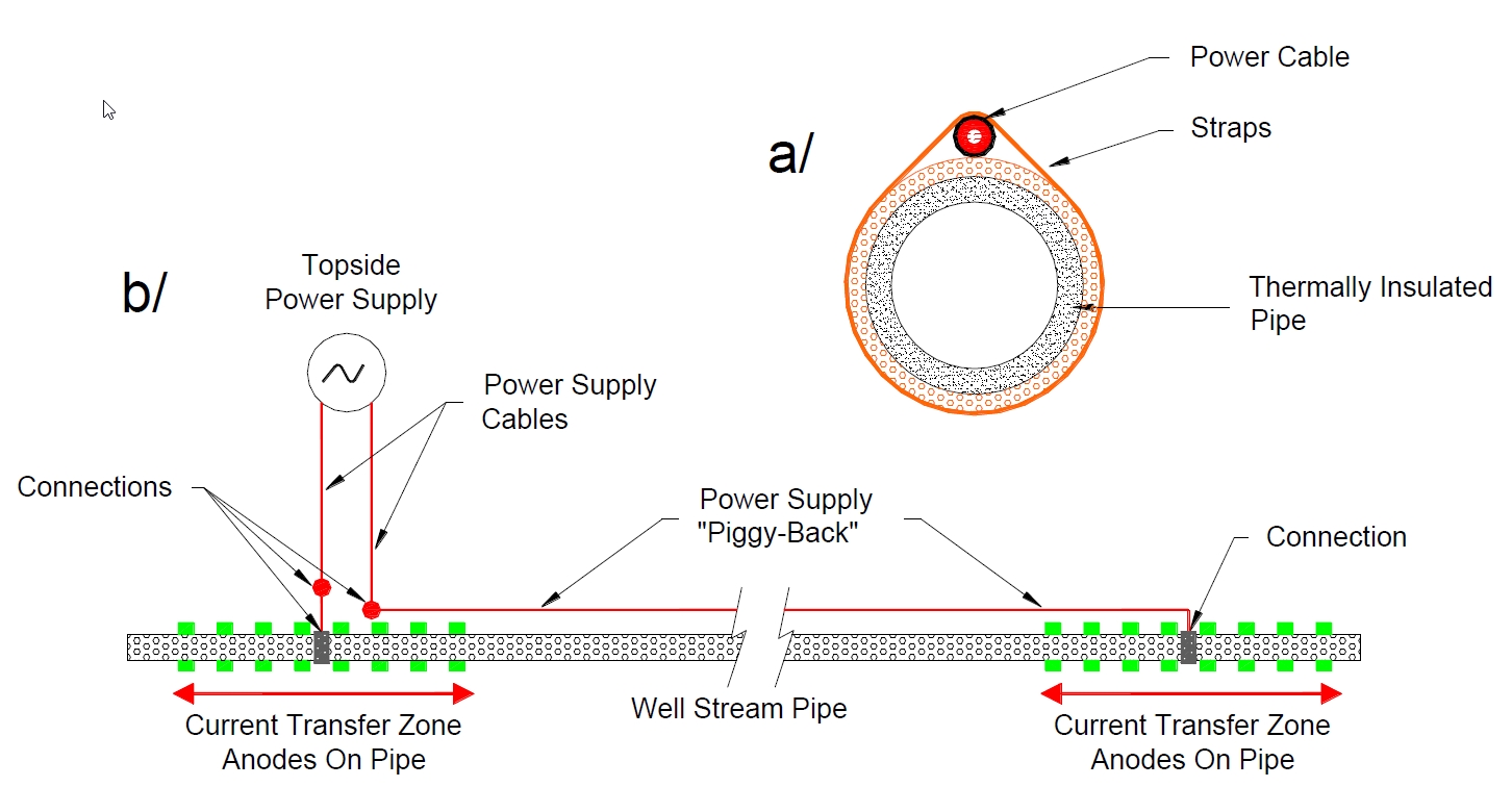
The following results can be drawn from the qualification test performed on 8-12" single rigid steel pipe:
No problems are foreseen for the concept on pipe dimensions up to 20"
The typical power requirement is 100-150W/m
The restriction concerning cable insulation level (36kV) limits the length of heated pipeline to 50km
No corrosion on normal carbon steel or 13%Cr steel pipes caused by the electric heating system is observed during qualification tests
7.3 Hot fluid circulation heating
For small to medium diameter risers requiring low heat compensation, the circulation of hot fluid (typically inhibited water) can be a cost effective and reliable alternative to the electric heating in deepwater applications.
The hot fluid circulation heating system consists in flowing hot water in external lines circumferentially installed on production risers (see Figure 7.2, “Hot water heated flexible riser” and Figure 7.3, “Hot water heated flexible riser”). The water is injected from the floating production system and dumped to sea (i.e. to save a return line).
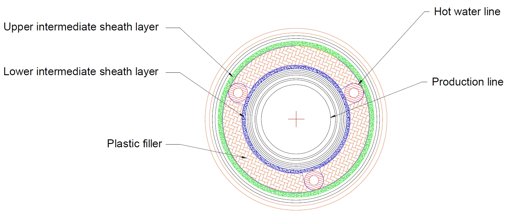
The heating lines are either in coiled tubing pipes or flexible pipes dependent on riser design criteria. The diameter and number of the heating lines will mainly depend on the dimensions of the riser to be heated up and the temperature variation between seawater and the produced fluid for different operation modes.
The heat transfer value between the heating lines and the production riser to be heated is low, but it can be improved by either creating a heating chamber with thermal insulation material or using a conductor material placed between them.
Examples of such bundles include Statoil’s Asgard and Gullfaks South, Conoco’s Britannia, and BP’s King. These bundles can be complex in design, and there are thermal design, mechanical design, fabrication, installation, lifecycle, and risk issues that need to be addressed.
7.4 Hot Oil Circulation
Hot oil circulation is a relatively common technique used to restart cold production systems. Hot dead oil is circulated through dual Flowlines and risers until they have warmed above hydrate conditions. Once the Flowlines and risers are warm, the wells can be restarted. The advantage of this technique is that it minimizes methanol usage over warming the Flowlines and risers with production. When the whole production system is warmed with production, methanol must be injected until it has warmed above hydrate conditions. At moderate to high water cuts, the methanol quantities can be prohibitive. This technique can also be used to keep the Flowlines and risers warm during a shutdown. If this is done, once the operators are ready to restart, the system can be started immediately.
7.5 Facility requirements
Facility requirements for active heating can include:
Power generation (also need to consider whether heating system will be part of the emergency power generation capability)
Power transmission and distribution (e.g. umbilical conductors, topside and subsea transformers, subsea electrical connectors)
Heat generation or waste heat recovery
Heat exchanges
Pumps and meters
Instrumentation
Active heating, with respect to EH or pipe bundles, adds complexity to the subsea design. The risks associated with active heating are derived from this complexity. Reliability and lifecycle issues are major concerns with such systems. For both EH and actively heated bundles, corrosion will be a major concern.


