
10 Artificial lift requirement
10.1 General
Artificial lift is required when the natural reservoir pressure is insufficient to lift the produced fluids to surface at economic production rates. This can occur in the event of water breakthrough at the wells (increasing the weight of the liquid column), low pressure at the reservoir or the production of low GOR heavy crude.
Artificial lift also helps to stabilise the fluid flow regime, and hence eliminate slugging in the production Riser.
Artificial lift may be a cost effective solution to develop satellite fields as it facilitates the transportation of produced fluids over longer distances, thus reducing the investment by simplifying the production layout and reducing the number of platforms. Furthermore, it increases field life and recovery rate.
The offshore oil and gas production is typically based on natural flow driven by reservoir pressure, water injection and artificial lift, whenever necessary.
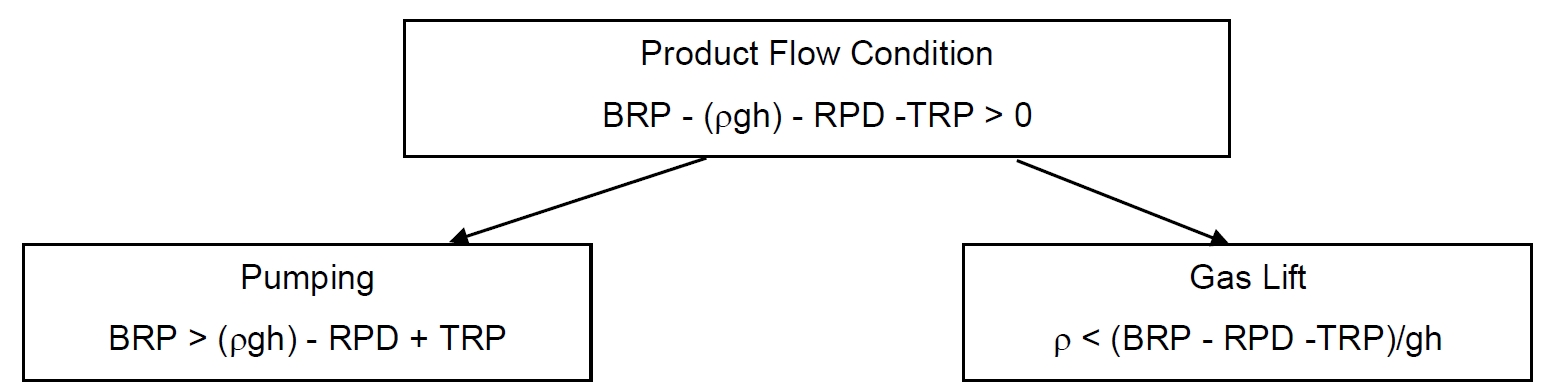
The flow rate requirement on top of the production riser is formulated as follows:

Where:
Or, in the case of riser Artificial Lift:

Where:
BRP = Bottom riser Pressure
HP = Hydrostatic Pressure = rgh (r effluent mixture & gas density along riser)
RPD = riser Pressure Drop
TRP = Required Top riser Pressure
In this formula, two terms can be adjusted to improve the flow rate:
The Bottom riser Pressure, which can be increased by adding a pump unit
The transported fluid density r along the riser, which can be reduced by gas injection. The lower is the injection point, the better is the lightened effect. Therefore, the injection point should be positioned close to the riser base.
The first method calls for electrical submersible pumping to perform the artificial lift whereas the second for gas injection.
The different artificial lift methods are listed below:
gas lift
electrical submersible pump
hydraulic jet pump
progressing cavity pump
multiphase pump
subsea separation system
The following covers only the gas lift method (i.e. the most cost effective solution) applied to rigid or flexible riser and hybrid riser tower having the gas injection point at the riser base.
10.2 Gas Lift Method
The gas lift method principle is to increase the flow rate by reducing the specific gravity of the producing fluids.
For subsea application only gas lift has been widely used as artificial lift method, due to its intrinsic similarity with onshore' s gas lift method. This similarity comes from the fact that it is driven by a power fluid using roughly the same components for both onshore and subsea application. For this reason, gas lift is today seen as the subsea conventional artificial lift method.
Sometimes, gas lift may not be the best method to fit specific field's requirements. This happens, for instance, when there are long distances between well heads and the host platform system, and the gas injected, even though helping the flow in the vertical sections (well and riser), increases pressure drops in the horizontal section of the Flowline. Additionally, this method demands compressors and an increase of gas facilities to handle the extra recycling gas, with consequent drawbacks on platform weight and space requirements, which have a high impact on offshore installation costs.
Other problems with the gas lift method are its contribution to the cooling of the producing fluid due to the gas temperature and expansion (Joule-Thomson effect) and a relatively low efficiency (i.e. a ratio between output and input hydraulic power of about 20%). The cooling of the produced fluid will aggravate the wax and hydrates formation problems.
The gas lift method hence requires to be early integrated in the riser design as a part of the riser system; this is especially true for concepts such as riser bundle or hybrid tower.
No difficulties, regarding the riser system definition, are expected when using the conventional gas lift method; the only requirement is the provision of a sufficient number of gas lift line. But an activated riser configuration requires additional studies, mainly due to the lack of experience. As the injection point is positioned on the lower part of the Riser, special studies must be conducted to precisely define the required equipment (valve, gas diffuser, etc.) and the consequences on the riser structure (reinforcement to increase high stress and fatigue resistance) and behaviour.
The gas lift method is characterised by two modes:
Internal mode: In this mode the gas lift method uses coil tubing introduced from the top of the riser to the riser base or gas lift lines circumferentially arranged around the riser (e.g. integrated flexible riser)
External mode: In this mode, each production line has its own gas lift line clamped to the outside diameter. The production lines can also be activated by a common gas lift line through the subsea manifold
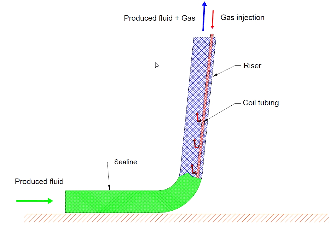
10.2.1 Internal gas lift using coil tubing
The artificial lift is performed by means of a coil tubing deployed from the inside of the production riser at the surface (see Figure 10.1, “Gas lift through coil tubing”). This method is well adapted to flexible and rigid riser.
The gas injection point can be selected by adjusting the length of the coil tubing. This solution requires one coil tubing per riser, which can also be used for the chemical injection.
The advantages and disadvantages of this solution are summarized in Table 10.1, “– Advantages & disadvantages of gas lift through coil tubing”:
Table 10.1 - – Advantages & disadvantages of gas lift through coil tubing
ADVANTAGES | DISADVANTAGES |
|
|
List of main equipment is provided in Table 10.2, “– Main equipment of gas lift through coil tubing”:
Table 10.2 - – Main equipment of gas lift through coil tubing
SURFACE EQUIPMENT | SUBSEA EQUIPMENT |
|
|
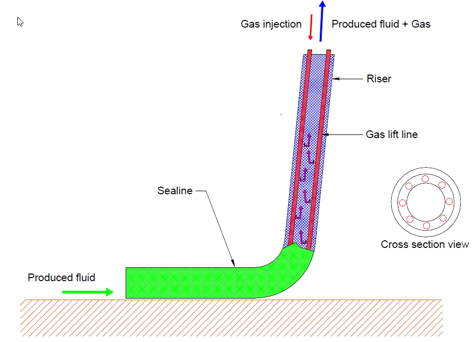
10.2.2 Internal gas lift lines integrated to production riser
In this method the artificial lift is performed by means of gas lift lines surrounding the production riser. The bottom end terminations of the gas lift lines are connected to isolation valve (s) controlled from the surface for safety reasons (see Figure 10.2, “– Gas lift line integrated production riser”). This technique is well adapted to flexible risers (i.e. TECHNIP-FMC Integrated Pipeline Bundle see section Section 5.2, “Flexible Riser Systems”).
The advantages and disadvantages of this solution are summarised in Table 10.3, “– Advantages & disadvantages of gas lift line integrated to production riser”:
Table 10.3 - – Advantages & disadvantages of gas lift line integrated to production riser
ADVANTAGES | DISADVANTAGES |
|
|
List of main equipment is provided in Table 10.4, “– Main equipment of gas lift line integrated production riser”:
Table 10.4 - – Main equipment of gas lift line integrated production riser
SURFACE EQUIPMENT | SUBSEA EQUIPMENT |
|
|
10.2.3 External gas lift line
The artificial lift of the produced fluid is made using gas lift at the riser base. The gas injection is performed from the surface to each production riser through a dedicated line.
Several solutions can be considered for the installation of the gas lift line:
Externally mounted on each production riser using the piggy back method (see Figure 10.3, “Gas lift line in piggy back”).
Inserted in the thermal insulation of the production riser.
Clamped to the central member of the hybrid Riser.
This technique is applicable for all type of risers.

The advantages and disadvantages of this solution are summarized in Table 10.5, “– Advantages & disadvantages of gas lift line in piggy back”:
Table 10.5 - – Advantages & disadvantages of gas lift line in piggy back
ADVANTAGES | DISADVANTAGES |
|
|
List of main equipment is provided in Table 10.6, “– Main equipment of gas lift line in piggy back”:
Table 10.6 - – Main equipment of gas lift line in piggy back
SURFACE EQUIPMENT | SUBSEA EQUIPMENT |
|
|
10.2.4 External common gas lift line
In this configuration, the gas injection point is also at the riser base. The gas is routed from the surface to a retrievable subsea manifold through a common gas lift line. The gas distribution is then made using hard piping or jumpers connecting the subsea manifold to the production riser (see Figure 10.4, “Manifold_based_gas” ).
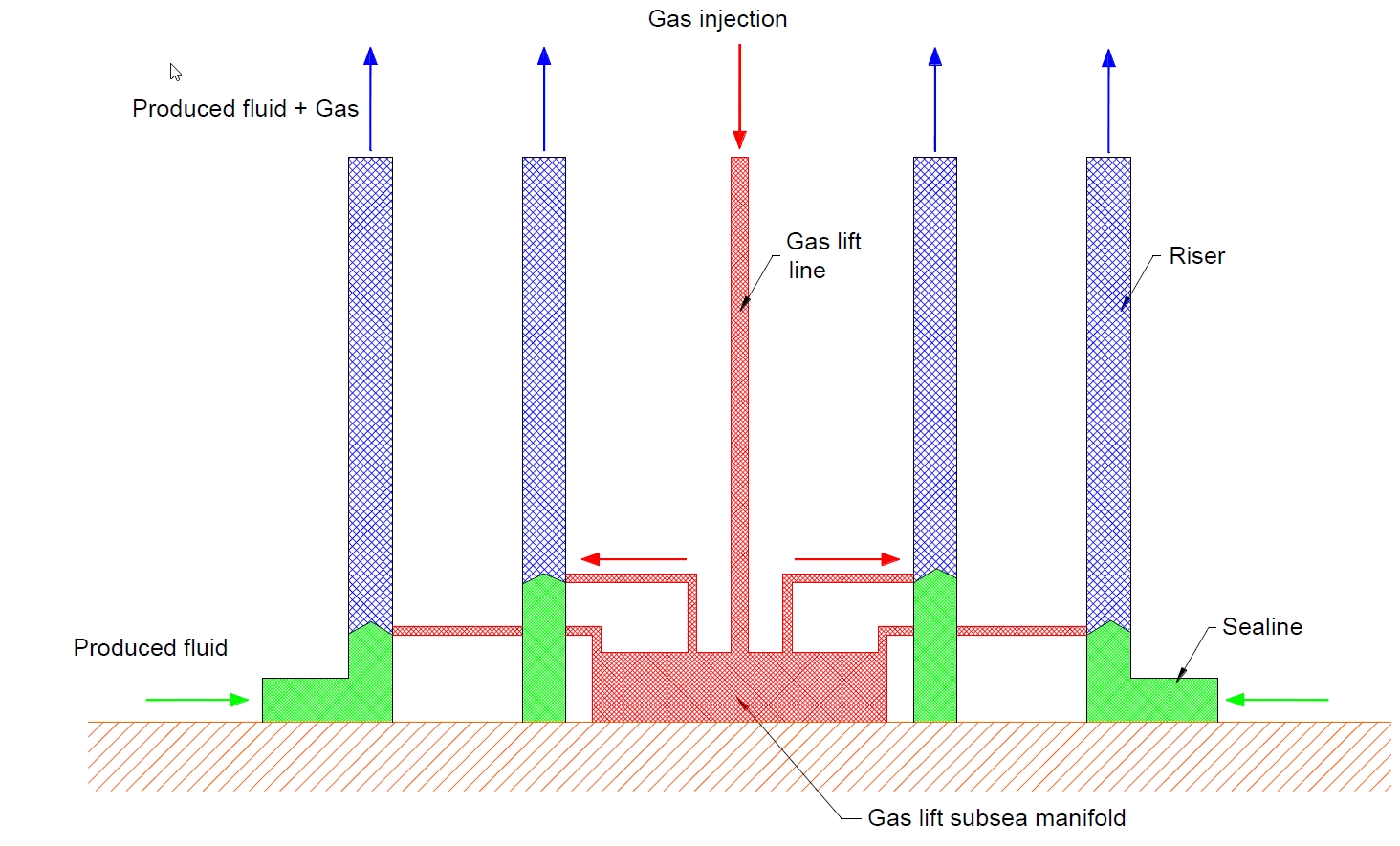
– Manifold based gas lift method
An alternative to the above solution consists to gather all gas lift lines together in a multi-bore line, which will be distributed at the riser base for the gas injection in the production risers.
In the first alternative, the gas injection is controlled from the surface by means of electro-hydraulic umbilical connected to the subsea manifold, whereas in the second solution, the control is done directly from the surface. This technique is applicable for all type of risers.
The advantages and disadvantages of this solution are summarised in Table 10.7, “– Advantages & disadvantages of manifold based gas lift method”:
Table 10.7 - – Advantages & disadvantages of manifold based gas lift method
ADVANTAGES | DISADVANTAGES |
|
|
List of main equipment is provided in Table 10.8, “– Main equipment of manifold based gas lift method”:
Table 10.8 - – Main equipment of manifold based gas lift method
SURFACE EQUIPMENT | SUBSEA EQUIPMENT |
|
|
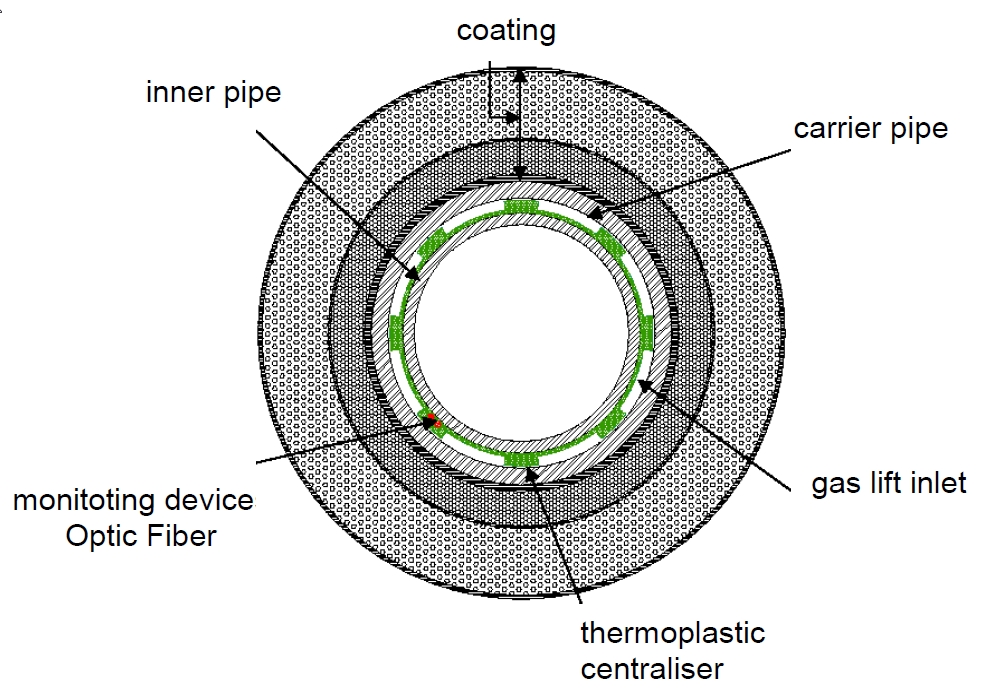
10.2.5 Gas lift through Pipe in Pipe annulus
A gas lift requirement to a riser can be achieved by a solution utilizing the pipe in pipe configuration, with the annulus conveying the gas injected at the top of the riser. The gas enters the production line inner pipe at the base of the riser. The two pipes are connected together at the riser string base via a bulkhead and at the top via a hanger spool. Centralizers are located along the string to avoid contact of the two pipes during the welding of the casing. The insulation on the riser is applied on the outer pipe of the pipe in pipe section.
Conveying the gas through the annulus of a pipe in pipe externally insulated is one of the most reliable solution in terms of flow assurance.
Gas lift injection through PiP annulus is used on following TOTAL developments : CLOV (production HRT), KAOMBO (production SHR) and EGINA (production SHR).
The advantages and disadvantages of this solution are summarised in :
Table 10.9 - – Advantages & disadvantages of pipe in pipe configuration
ADVANTAGES | DISADVANTAGES |
|
|
List of main equipment is provided in :
Table 10.10 - – Main equipment of pipe in pipe configuration
SURFACE EQUIPMENT | SUBSEA EQUIPMENT |
|
|


