
4 Interface requirement
4.1 General
Interface engineering and management is a key topic in riser design to ensure its ‘fit-for-purpose’ with regard to interface equipment such as:
Pipeline end terminations
Subsea production systems
Subsea connection and tie-in methods
Lay vessel capabilities, lay equipment specification and methods (e.g. J-lay, reel lay, towing)
Attachment point (riser hang-off) on the floating production system
Anchoring point at the seabed, as required
This document will address only the two last topics as the other subjects have already been covered in the documents referenced , and .
4.2 With Floating Production System
Considering FPS such as semi-submersible, SPAR or TLP, the hang-off point can be either at the pontoon level or at the deck level with the following advantages and drawbacks:
Interface at pontoon level allows the riser to avoid the dynamic wave splash zone, hence avoiding high environmental loads and eliminating the risk from accidental vessel impact. This solution has the disadvantage of involving subsea connection, which complicates the connection installation, inspection and maintenance.
A deck level hang-off point has the advantage of being an above water connection. However it require the riser to pass through the splash zone and increases the reversal efforts applied on the floating production system (as riser tension is applied above the centre of buoyancy) with a consequent impact on stability and payload.
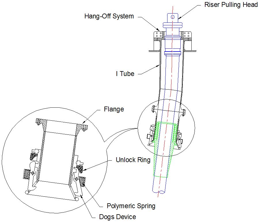
For flexible riser, a hanging device (e.g. ‘I’ or ‘J’ tube) is fixed to the floater and used to maintain the top of a riser at floater main deck level. The ‘I’ or ‘J’ tubes are designed to protect the riser against environmental loads (wave and current) and accidental collisions with vessel (see Figure 4.1, “Top attachment arrangemet of flexible riser”). They are often equipped with a bell mouth system using mechanical dogs to hold the riser bending stiffener with a conical structure facilitating the riser entry and allowing angle deflection.
For rigid riser hung in a free catenary configuration, a flex-joint receptacle fixed to the pontoon or deck level acts as a hanging point (see ???).
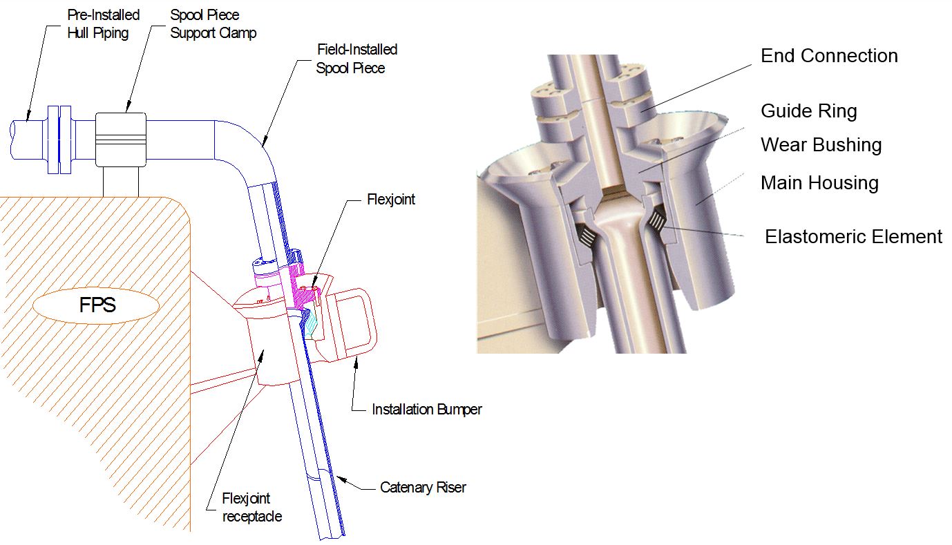
For SCR developments, the design of flex-joint systems has generally only accounted for observed rotations (maximum and ranges (for fatigue issue)). However, the use of flex-joints for ultra deepwater applications requires the flex-joint designer to consider the effects of the large SCR hang-off tensions and similarly the tension ranges for fatigue design, combined with the produced fluid chemistry (e.g. elastomeric product corrosion, ageing) as part of the overall flex-joint design and qualification.
Recent failures with flex-joints have prompted the industry to investigate the feasibility of using stress joints as the SCR/platform interface instead of flex-joints. The lessons learned from this failure investigation should be implemented into all existing and future planned developments.
The ability to retrieve the SCR with the flex-joint attached to the deck should be considered as a mechanism for the SCR designer to enable detailed inspection. The implementation of a risk based integrity management plan could address the periodic inspection/monitoring of the flexjoint to minimise the risk of failure during the field life.
For the top-tensioned risers, a tensioning system is required to support the riser, maintain required tension and compensate for the relative motions of risers and platform.
From a semi-submersible platform, riser is typically supported by hydro-pneumatic cylinders and lines rigged through sheave blocks to magnify the movement of the cylinders and so allow large relative motions between the platform and the riser.
The amount of relative motion between the TLP and the riser is small and simple hydraulic/pneumatic cylinders may be connected directly to the riser at the special "riser tensioner joint".
In a SPAR platform, the risers will only require a simple static tensioning system to be used mainly during the riser installation. Once the desired mean tension is achieved the risers may be locked off with the buoyancy cans attached to the riser and compensating for the platform movements (see Section Section 5.3.2.2, “Top Tensioned riser applied to TLP and SPAR”).
4.3 At seabed
The free hanging (rigid or flexible) catenary riser system is characterised by the absence of additional hardware components except at the seabed connection to a steel Flowline. This Flowline (or Sealine) can be terminated by either a mechanical connector or by a pipeline end manifold (PLEM) in this case a flexible or rigid jumper installation would be required.
![[Tip]](tip.png) | Tip Click these links below for access to 3D resources: |
In the other configurations and depending on the type of risers, the following subsea interfaces are required:
4.3.1 Flexible risers
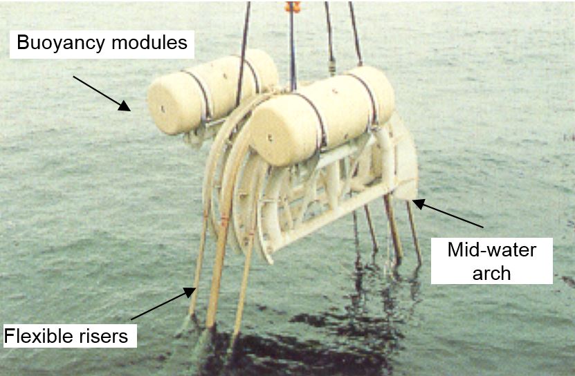
In order to increase the riser system compliance (particularly in relative shallow waters), the Lazy "S" and Steep "S" configurations can be adopted (see Section ). Mid-water arches are used to support the risers in these configurations (???). The mid-water arch and buoyancy modules are restrained by means of slings and dead weight in the lazy "S" configuration (Figure 5.12) and in the Steep "S" configuration (?) the flexible pipe would sustain the buoy system tension.
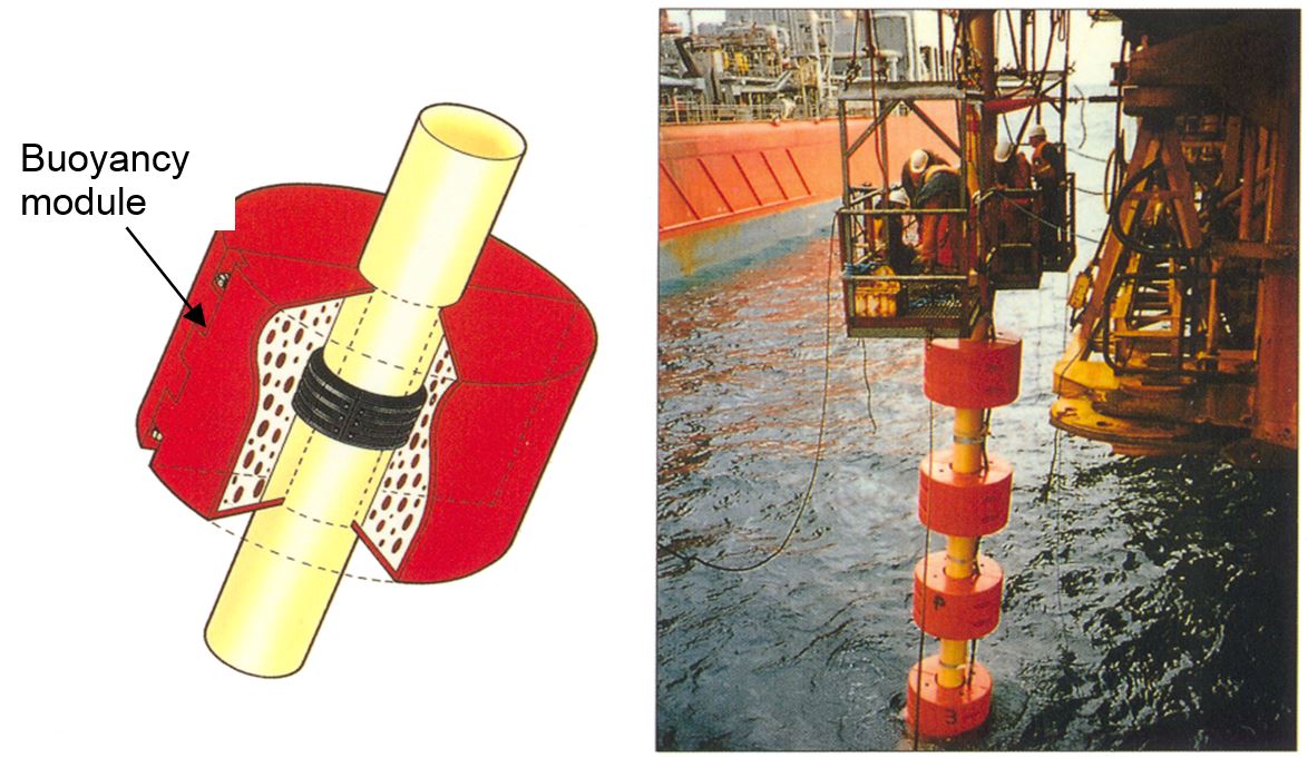
In the ‘wave’ configurations (lazy-wave, steep-wave) the mid-water arch is replaced by distributed buoyancy modules consisting of two parts (see Figure 4.4, “Distributed buoyancy modules being installed on flexible riser”):
A steel clamping system which ensures the attachment of the buoyancy module to the flexible.
A buoy with a torus shape. The material used for this buoy (usually syntactic foam) is designed according to the water depth.
The anchoring base of a riser in Steep "S" or Steep "Wave" configuration consists of a steel and/or concrete structure. It may include piping, valves and elbows (see Figure 4.5, “Typical riser base for Steep system”).
The soil conditions are an important parameter. In fact, the angle of the subsea end fitting of a riser in a Steep "S" or Steep "Wave" configuration has to be carefully controlled and depends on the riser base being horizontal (+/- 2°). The riser base is generally stabilised by its own weight (gravity base) but can be piled if soil conditions so require.
| Tip Click these links below for access to 3D resources: |
4.3.2 Top tensioned risers
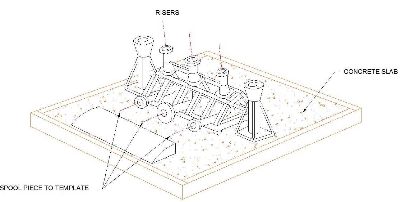
Figure 4.6 - Riser base mounted on subsea template
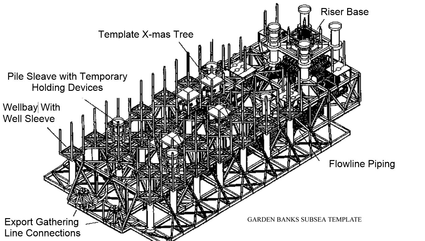
For the top tensioned risers, the riser base is a steel structure mounted on a well template or a subsea manifolding template and equipped with a male hub facing upwards for connection to the riser by means of tie-back connector (see Figure 4.6, “Riser base mounted on subsea template”).
4.3.3 Hybrid riser tower
A riser tower is anchored on the seabed by means of a riser foundation to resist tension loads. In addition, this riser base acts as a connection point to the subsea Flowlines and end manifolds.
The riser base-foundation may be piles (steel), gravity (concrete) structures, suction caisson or a combination thereof. Typical installation inclination relative to vertical is +/- 2°.
| Tip Click these links below for access to 3D resources: |


