
5 riser system review
5.1 General
A riser system must be selected and designed to the following requirements:
Provide enough flexibility to allow for FPS motions due to :
First order wave motions.
Second order wave motions (slow drift).
Static offset due to environmental loads.
Static offset after mooring line failure.
Acceptable behaviour under environmental conditions encountered (i.e. resists to the environmental loads and especially current loads, avoids riser clashing, and overreaching of the maximum loads which can be withstood by the floater or the riser base).
Satisfy the flow assurance requirements:
Sufficient insulation or heat supply.
Resistant to the fluid aggressions (i.e. internal pressure, corrosion, erosion).
Artificial lift means if required (e. g. gas-lift, multi-phase pump)
Resist to transportation/laying loads (i.e. external overpressure, clamping pressure, etc.).
A wide range of riser configuration concepts have been designed and sometimes applied. Variations occur due to the specific requirements of each application. These configurations can be distinguished on the basis of:
The structural properties of the riser section (i.e. rigid or flexible) and the materials
The cross-section complexity (i.e. mono-bore or multi-bore)
The general arrangement/configuration.
5.2 Flexible Riser Systems
5.2.1 Structural description of flexible pipe riser
I. Monobore flexible pipe
Non-bonded flexible pipe has been applied in the offshore oil and gas industry for more than 25 years. It is used for dynamic risers connecting seabed Flowlines to floating production systems, and for (static) seabed Flowlines. In some cases flexible pipe has proved to be more economic than rigid pipe: in harsh environments or when it is desired to recover the Flowline for re-use after a short field life.
The flexible pipe design (see Figure 5.1, “Non-bonded flexible riser construction”) consists of a stainless steel internal carcass for collapse resistance, an extruded polymer fluid barrier, a carbon steel interlocked hoop strength layer, helically wound carbon steel tensile armour for axial strength, and an extruded watertight external sheath. For dynamic applications extruded polymer or tape polymer anti-wear layers are applied between adjacent steel armour layers. For extremely high pressure applications, an additional layer of rectangular shaped helical reinforcement over the interlocked hoop strength layer, or a second set of tensile armour layers, may be applied. The flexible pipe structure is inherently thermal resistant and corrosion resistant. Thermal insulation layer(s) can be added under the external sheath to provide additional thermal resistance.
The flexible layers are depicted on the following Figure 5.1, “Non-bonded flexible riser construction”:
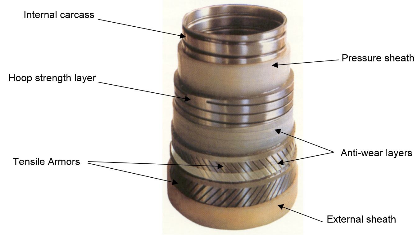
Internal Carcass: the interlocked carcass main function is to provide collapse resistance. A flexible pipe featuring a carcass is a ‘rough bore’ pipe, versus the smooth bore pipe.
The pressure sheath provides leak profess and act as a fluid barrier
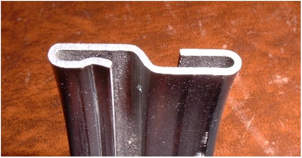
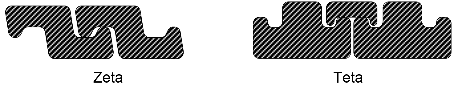
The pressure vault function is to give hoop resistance. Two profiles (Zeta and Teta) were successively developed to cope with the increasing fluid pressure requirements.
The armours main function is to resist tensile loads.
The external plastic sheath protects the inner layers from shocks, etc.
The main materials used in flexible pipe fabrication are outlined in following Table 5.1, “Materials used in the flexible structure”:
Table 5.1 - Materials used in the flexible structure
Designation of layer | Material used |
Thermoplastic tube | Polyamide 11, High Density Polyethylene, Coflon |
Interlocked steel carcass | Galvanized steel, AISI 3O4, AISI 304L, AISI 316, AISI 316L, Duplex, FI41, FI42, etc. |
Thermoplastic pressure sheath | Polyamide 11, High Density Polyethylene, Coflon, Gammaflex |
Teta spiral or hoop strength layer | Low or medium carbon steel |
Reinforcing layer | Low, medium or high carbon steel |
Thermoplastic friction sheath | Polyamide 11, High Density Polyethylene |
Double crosswound armours | Low, medium or high carbon steel |
Insulation foam | Cofoam, Carazide, hollow glass microspheres – macrospheres + resin binder |
Latest improvements in the flexible pipe technology, to cope with the ultra-deep water stringent requirements include:
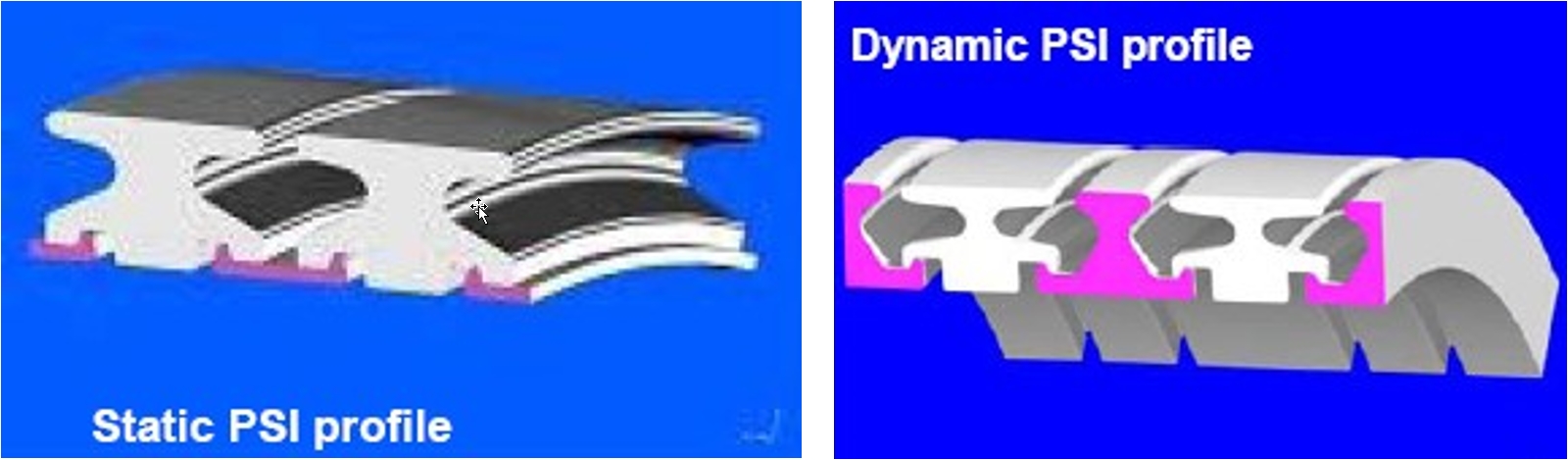
Development of a new pressure vault profile: ‘PSI’ sections for both static and dynamic applications.
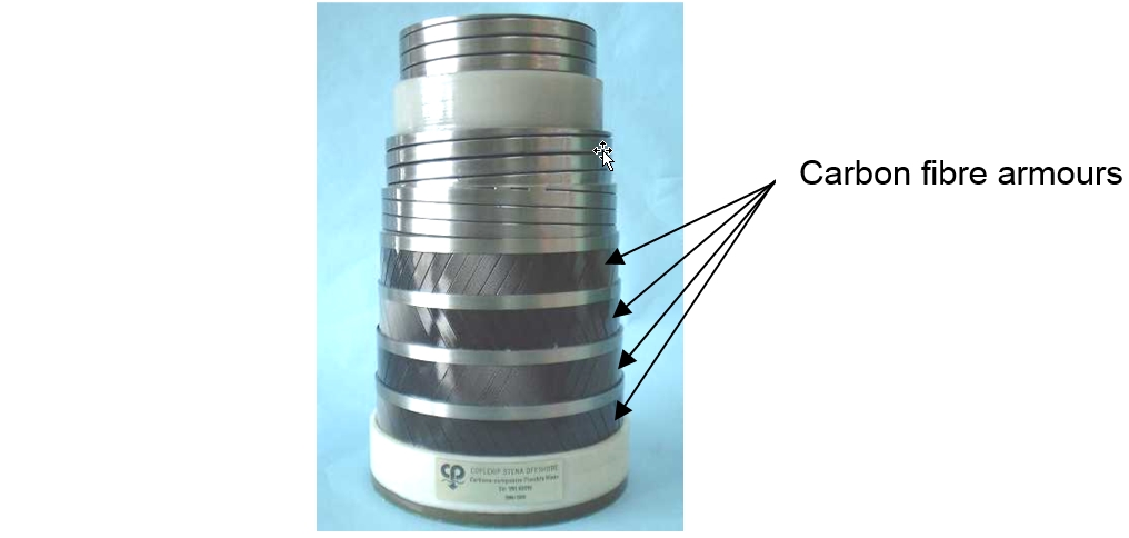
Use of carbon fibre for the tensile armour design aiming at riser weight/tension reduction.
The application of current flexible pipe technology in ultra-deep waters may be restricted by (a) water depth, (b) fluid pressure and temperature, (c) fluid chemistry and corrosion (pH, H2S, CO2).
These parameters are interdependent and also vary with the flexible pipe diameters. Typical maximum values (under development) are: 10kpsi, 150°C, 11”ID for 1800m water depth application.
The following figure shows typical current and future capabilities for ultra deep water flexible pipe.
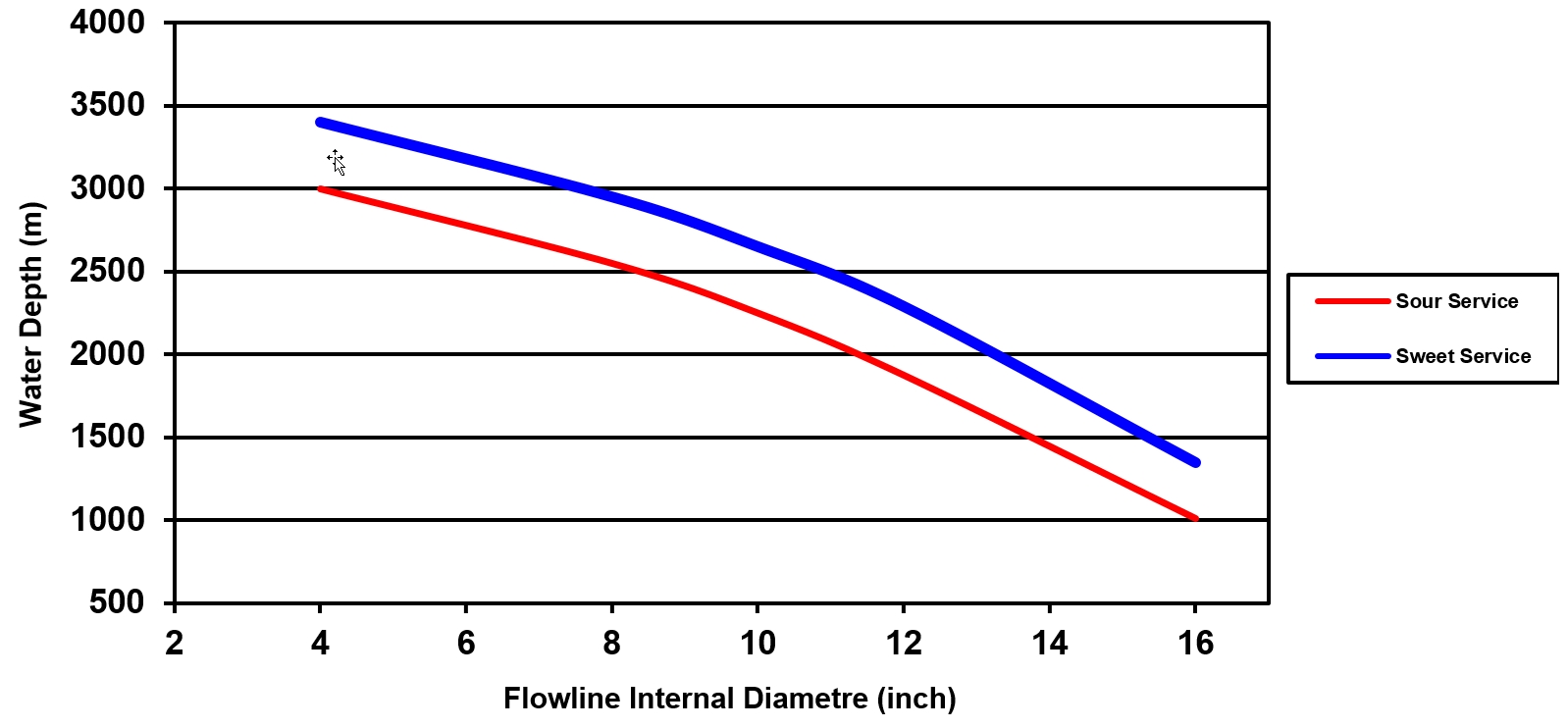
![[Note]](note.png) | Note Maximum water depth based on the following basis,
|
Flexible riser free hung from the FPSO may provide the solution to the harsh environmental conditions of the Gulf of Mexico. However large diameter flexible pipes (>10"ID) suitable for service in 3000m water depth, are still not available. At such depth, the flexible riser diameter is limited by hydrostatic collapse (reversed end-cap effect) and/or excessive hang-off tension.
Some studies have shown that collapse rating is not the only limiting factor in ultra deepwater. Rather the challenge of a traditional free hanging catenary riser configuration is the top tension load and the compression load at the touchdown point.
II. Integrated Production Bundle
The IPB is a flexible riser assembly incorporating active heating, gas lift hoses, monitoring fibre optics and passive insulations. The integrated heating system is proposed to prevent hydrate blockage by maintaining a minimum bundle temperature. It can be considered as a riser concept to face stringent flow assurance requirement.
An IPB (see ???) comprises primarily the following components:
The core, which is a ‘standard’ flexible pipe structure for production fluid transportation
The external assembly which is a bundle of tubes, hoses, cables and fillers wrapped in ‘SZ’ configuration around the core.
The insulation material is typically syntactic polypropylene foam. The insulation layers can either be made of spiralled strips or either made of thick fillers assembled in S-Z around the core structure.
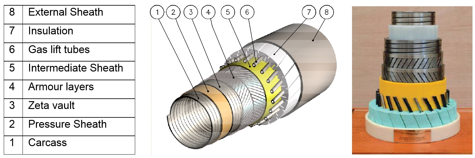
The IPB thermal insulation is provided by the different flexible pipe intermediate layers and the insulation layer (layer 7 of ???). Depending on the required thickness of this insulation layer, it can be composed either of spiralled strips or extruded bars laid in SZ.
The IPB can be actively heated either using the hot water method (through some of the tubes of layer 6) or electrical heat tracing (Joule effect) method.
Other possible functions can be incorporated through the bundle (layer 6), such as:
Power Cables
Monitoring (optical fibres sensors)
Hydraulic Hoses
The assembly provides a number of advantages to the IPB:
Combines passive insulation and active heating with flexibility in order to minimize the potentially significant thermal losses that can occur along the height of a Riser.
Integration of several lines in a single multibore pipe reduces considerably the congestion of the riser system and the subsea equipment and the risks associated with the offshore installation operations.
Integration of gas lift/injection tubes improves the thermal performances of the bundle because the injected gas is "hottest" at the coldest location i.e. the top section.
Addition of an optical fibre distributed temperature system (DTS) allows the real time monitoring of the temperature system along the riser.
IPB provided by TECHNIP-FMC represents the latest flexible pipe technology and has been selected for Dalia field in West of Africa.
5.2.2 End fitting
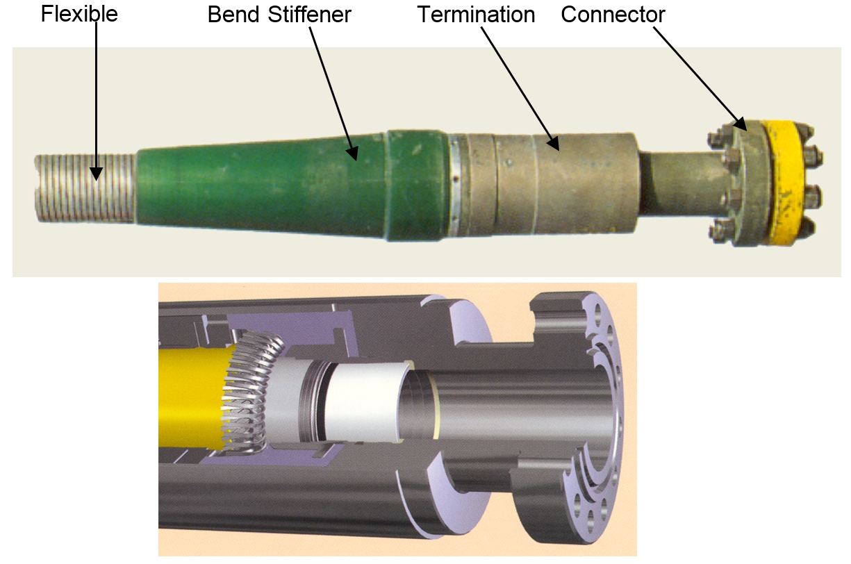
Flexible riser is terminated with two end-fittings composed of (see Figure 5.8, “Flexible pipe end fitting”):
The termination which ensures the seal and the mechanical attachment of the end-fitting to the flexible pipe
The connector to allow the connection of the end-fitting to any other compatible connector. All types of connectors can be supplied with end-fittings, the most common being API hubs (formerly "CIW hubs"), hammer unions and flanges.
5.2.3 Bending stiffener
In dynamic risers, the smallest bending radii (i.e. higher bending moment) are generally found near the end fittings at the connection with the floating production system.
In order to avoid any over-stressing of the flexible pipe at this location, moulded plastic bending stiffeners are placed around the riser (see Figure 5.9, “Bending stiffener mounted on riser”). Their conical shape ensures a smooth transition between the end fitting and the riser.
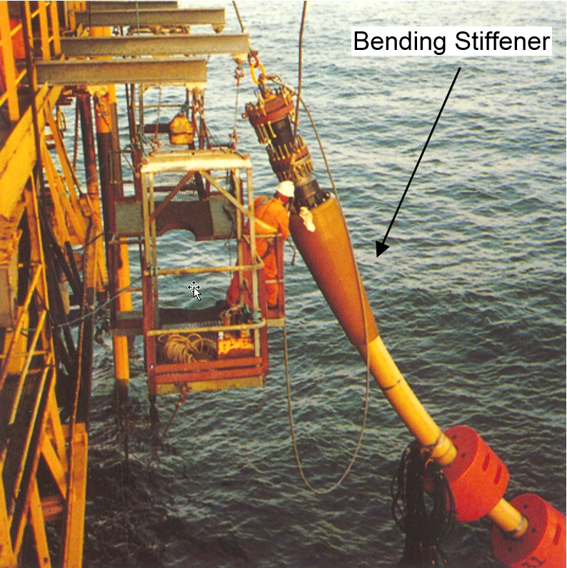
However, traditional stiffener design adopts metallic internal components (except the stiffener flexible body) which are in permanent contact with the riser outer sheath. Some field problems related to excessive wear at the top section of the risers, leading in some cases to external sheath tearing. The loss of water tightness severely increases the corrosion effects in the armours wires.
In order to solve the wear problem or at least to minimize the riser outer sheath damage, new solutions of bending stiffeners are being studied:
Use of an anti-wear sleeve inside the bending stiffener, in order to avoid direct contact between metallic parts and the riser outer sheath.
Connection of the bending stiffener directly to the riser armour pot, in order to avoid the relative displacement between the stiffener and the riser outer sheath (hence, the stiffener is no longer fixed at the I-tube lower end and it is free to slide inside the bell mouth).
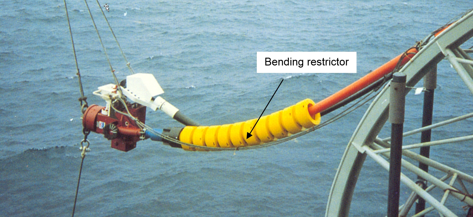
5.2.4 Bending restrictor
A bending restrictor is made of several vertebrae which physically limit the curvature of the flexible pipe to an admissible radius (see Figure 5.10, “Bottom end riser termination equipped with a bending restrictor”). The bending restrictor is used mainly:
At the bell mouth of a J tube (e.g. to control the bending load and the minimum bending radius).
At the horizontal connection of a wellhead or a template, when the distance between the connection and the sea-bed is important (i.e. to control the bending radius)
As external protection for the flexible pipe (e.g. when crossing a large diameter rigid pipe).
In order to avoid any over-bending during installation, generally when the flexible is connected to a structure (plem, automatic connector, skid, etc.) before installation.
5.2.5 riser configurations
Flexible risers have been used extensively for floating and early production systems. Such risers offer the advantage of having inherent heave compliance in their catenary shape, thereby greatly reducing the complexity of the riser-to-rig and riser-to-subsea interfaces. In shallow waters and mild environments the risers have been used in a simple catenary configuration. With increasing water depths coupled with severe environments several alternate configurations have been used and proposed, namely, the Lazy S, Steep S, Lazy wave, Steep wave and Pliant wave.
These different configurations are available on a custom design basis. The choice of the adequate configuration is made according to different parameters such as:
|
|
The different flexible riser configurations are described below:
5.2.5.1 "Free Hanging" configuration
(see Section 5.2.5.1, “"Free Hanging" configuration”)
This is the configuration of a flexible riser which runs in a catenary shape from the upper connection point on the floater straight down to the seabed where it can be connected to any of subsea equipment (flexible Sealine, PLEM, satellite tree, subsea manifold, etc.).
– Flexible riser in "Free Hanging" configuration
The Flowline system can be either all flexible pipe, or a combination of rigid Sealine and flexible riser. The installation of a flexible riser / rigid pipe consists in basically, after a steel pipe has been installed and abandoned on seabed, retrieving the rigid line by the flexible pipe lay vessel and connecting above surface a flexible Flowline end segment. The entire assembly is then lowered to the seabed and the continuation of flexible Flowline installation continues till the transfer of riser Flowline to the floating production system.
At seabed sagbend location, the FPS first and second order motions can induce compression buckling in the flexible, or problem of pipe embedment in soft soil, especially in the case of an FPSO. If this appears to be critical, the solution may be to adopt another riser configuration such as "Wave" or "S".
All risers in the Albacora Leste Field (Campos Basin, Offshore Brazil) which will be on stream in 2006 are flexible and installed in free hanging configuration due to the field water depth (800-2000m), the FPSO anchoring type and the pipe diameters ranging from 4" to 9.13".
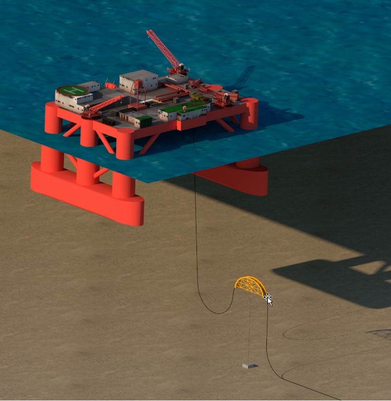
5.2.5.2 "Lazy S" configuration
(see Figure 5.11, “Flexible riser in "Lazy S" configuration”)
This is a configuration where a dynamic flexible riser runs down to the sea bed in a double catenary shape from the upper connection on the floater via a subsurface buoy, and a mid-water arch. The lower part of the flexible riser lies on the sea bed. The mid-water arch and buoy are tensioned by means of a sling and dead weight. The mid-water arch keeps the flexible riser at an acceptable curvature.
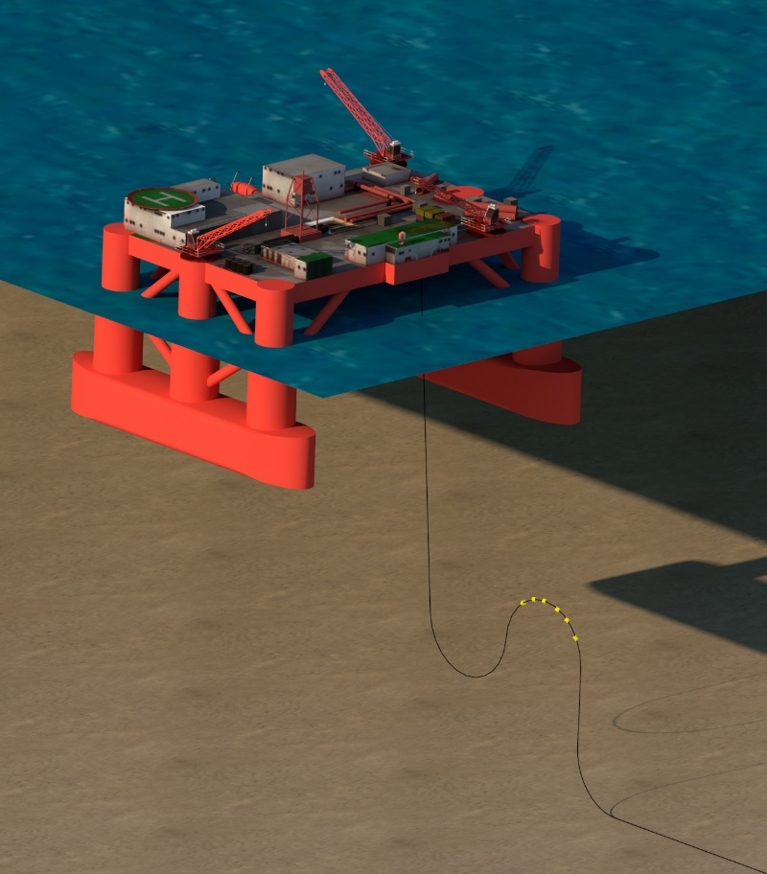
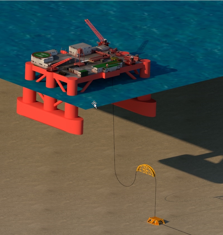
5.2.5.3 "Lazy Wave" configuration
(see Figure 5.12, “Flexible riser in "Lazy Wave" configuration”)
This is a configuration where a loop is formed between the upper connection and the seabed by clamping buoyancy modules along a given section of the dynamic flexible riser. The lower part of the riser lies horizontally on the seabed. The Lazy Wave configuration is a straight forward extension of the classic Lazy S configuration where the mid-water arch, and associated subsurface buoy, sling and dead weight are replaced by a number of buoyancy modules.
![[Tip]](tip.png) | Tip Click these links below for access to 3D resources: |
5.2.5.4 "Steep S" configuration
(see Figure 5.13, “Flexible riser in "Steep S" configuration”)
This is a configuration where a flexible riser runs down to the sea bed in a catenary from the upper connection on the floater, via a subsurface buoy and mid-water arch. The flexible riser itself is tensioned by the subsurface buoy and the mid-water arch, and is connected to a riser base at the subsea connection point.
5.2.5.5 "Steep Wave" configuration
(see Figure 5.14, “Flexible riser in Steep Wave configuration”)
This is a configuration where a loop is formed between the upper connection and the seabed by clamping buoyancy modules along a given section of the dynamic riser base. The lower part of the riser is connected to a riser base.
The Steep Wave configuration is a straight forward extension of the classic Steep S configuration where the mid-water arch and associated subsurface buoy are replaced by a number of buoyancy modules.
The Steep wave configuration is perfectly adapted to the Early Production and Testing vessel concept. The basic idea behind this concept is to simultaneously generate reservoir data through extended well testing and provide early cash flow by export of the produced crude/gas. Such a vessel is typically used for a few months on a field where reserves are not yet known with the accuracy required for the definition of a comprehensive development scheme.
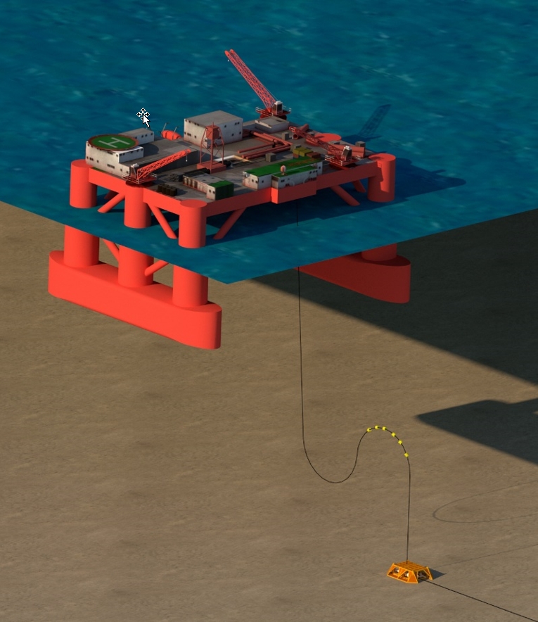
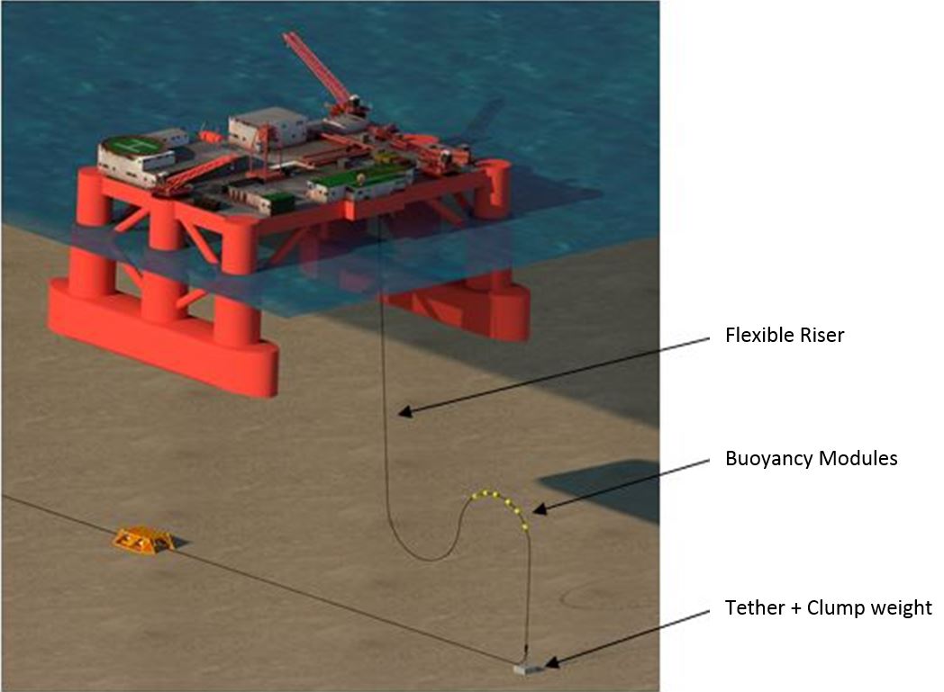
5.2.5.6 "Pliant Wave" configuration
(see Figure 5.15, “Flexible riser in Pliant Wave configuration”)
This is a configuration where a loop is formed between the upper connection and the seabed by clamping buoyancy modules along a given section of the dynamic flexible riser. The lower part of the riser lies horizontally on the seabed. One end of the lower part is connected to the subsea production system and the other end is attached to a dead weight to withstand the uplift generated by the buoyancy modules.
This configuration is well adapted to a field development using a floating production platform located directly above the subsea production system and flexible lines to connect the subsea wells to the floater.
5.3 Rigid pipe riser systems
5.3.1 General
Flexible risers have been extensively used for the field development based on floating production systems (i.e. semi-submersible, FPSO). With the increase of water depth, there are technical and economic limitations in the manufacturing of large diameter flexible risers: collapse due to high hydrostatic pressure, reverse end cap effects, etc.
A rigid steel riser system can provide a technical and cost effective alternative to the high procurement cost for flexible lines, which cannot always compensate for their lower installation costs.
5.3.2 Riser configurations
The main rigid pipe riser system configurations are:
| Tip Click these links below for access to 3D resources: |
5.3.2.1 TopTensionedriserTower applied to Semi-Submersible
(see Figure 5.16, “Top tensioned riser applied to semi-submersible (Enserch Green Canyon)”)
This riser configuration has been implemented by Enserch Exploration Inc on Green Canyon block 29 (470m WD) in 1988, recovered for refurbishment in 1990 due to reservoir declared non-commercial, and reinstalled on Copper Garden Banks 388 (640m WD) in 1995 in the Gulf of Mexico.
This Top Tensioned riser utilises a rigid, buoyant production riser with a titanium stress joint at the base. Titanium was selected for the stress joint material due to its reduced modulus of elasticity (about half of the steel Young's modulus) and its resistance to the fatigue and the effects of corrosion in sea water. The riser, connected at its base to a multi-slot template, provides individual access and surface control to each well and can remain connected throughout the life of the field including 100-year storm conditions. The top of the riser is located 55m below sea level and is connected to the floating production system by tensioning tethers. The depth of the riser top is selected to minimise the action of the waves and still allow air divers to work at that level. Flexible Flowlines and umbilical make the connection between porches mounted on the rig pontoons and the upper riser connector package on top of the riser. The rigid riser is installed in a manner similar to conventional drilling riser running techniques. The production, annulus, oil and gas export lines use standard tubing and line pipe and all are installed into the riser through the rotary table using conventional methods.
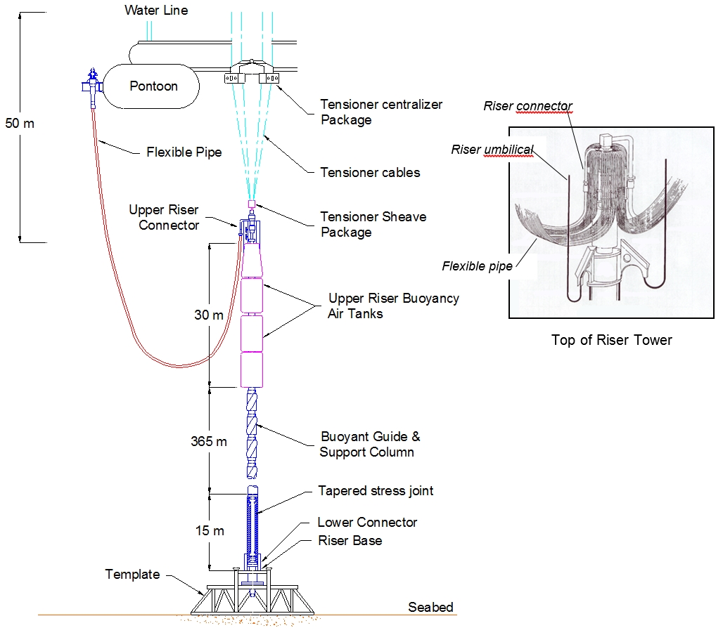
The Top Tensioned riser consists of the following main components from the bottom to the top:
The Enserch Green Canyon riser tower components are described below:
Riser base
The riser base consists of a hub profile centered between four radially located posts and four pile sleeves. Vertical female receptacles surround the hub to provide production/annulus/oil export line connections to the riser. Within the central hub connection, at a slightly lower elevation than the others, is a vertical receptacle for the gas export line.
Lower riser connector
The lower riser connector provides the structural link between the riser stress joint and the riser base at the template. The connector will transmit the tensile and bending loads from the riser to the riser base. The lower riser connector guides the riser onto the riser base and orients the riser for subsequent installation of the production annulus and export tubing. The connector allows the riser to be hydraulically locked to the riser base during installation and released for retrieval.
The connector is a field proven collet type connector which is modified to increase its bending capacity. The centre section of the connector has a stinger which extends into the mating hub to provide a moment carrying interface. This allows the collet segments to carry all tensile loads and only a portion of the bending moment.
Titanium Stress joint
The stress joint provides required flexibility and stress reduction between the riser connector and lowermost riser joint. Steel transition spools at each end have flange - hub connections. The lower flange connects to the lower riser connector, while the hub clamps to the stress joint. The upper spool hub clamps to the tapered end of the stress joint, while a bolt flange connects to the lowermost riser joint.
Riser joints
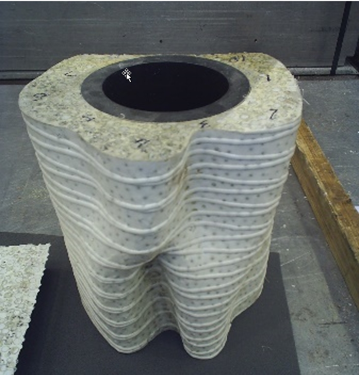
The rigid riser is constructed of long bolt flange to flange steel joints. When fully assembled the riser has sufficient buoyancy to make it free standing so as to reduce the deck loads on the vessel. This buoyancy is provided by three separate methods. Each individual joint has passive syntactic foam, which offsets the weight of each riser joint. The syntactic foam made the joints lightly negatively buoyant in seawater. In addition to the syntactic foam modules, each joint has an independent internal air can which provides air buoyancy to offset the weight of the production and annulus tubing. The air cans can be filled through an umbilical or independently filled or vented by an ROV. Five large air tanks are installed near the top of the riser. These tanks provide the buoyancy needed during the installation phase, and also allows the riser to withstand 100year storms and loop currents, even when it is disconnected from the rig.
Fiberglass guide tubes (to guide the production lines) are moulded in the syntactic foam modules mounted around the structural member. Each joint has twelve quarter sections of foam.
On the outside of each foam module are attachment points for vortex strakes and umbilical guides that are bolted and banded in place as joints are run through the moonpool.
Bolted to the uppermost riser joint with a flanged connection is the upper riser mandrel, which acts as the structural connection between riser and the upper riser connector package. The assembly includes a hub profile at its upper end surrounded by a guide plate to locate riser guide tubes for Flowlines and four guided posts to align the upper riser connector package.
Upper riser connector package
The upper riser connector package acts as the interface point between the rigid riser and flexible Flowline jumpers to the rig pontoon. It is locked in place by a collet connector at its lower end.
Around the main collet connector are "mini" collet connectors that lock to the annulus and production lines when the upper riser connector package is landed on the riser. Goosenecks attached to the mini-connectors make an 180-degree bend and terminate in a clamp hub facing down. Flexible lines are attached to these hubs and hang in a catenary shape to pontoon connection points on the floater. The export line is also located radially from the central collet connector with a similar connector.
In normal operating conditions, the mini-connector/gooseneck assemblies are each free to move independently in the vertical direction. This movement is necessary to compensate for vertical tubing deflections due to riser deflection, temperature effects, and pressure effects.
Riser tether system
Although the production riser tether system utilises drilling tensioned components, it is more accurately described as a riser centraliser than as a riser tensioner. The riser is free standing and does not depend on the tensioner for structural support.
If the floater moves away from the top of the rigid riser by the environmental forces, the flexible Flowlines take a shallower catenary curve. Without the restraint of the tensioner system, the flexible Flowlines would have to be significantly longer to prevent damage to their terminations and would consequently cause greater stresses in the riser due to increased weight and drag.
Applying a restraining force to the top of the rigid production riser and limiting its motion relative to vessel keeps the flexible Flowlines to an optimum length and allows them to remain connected during the most severe environmental conditions. The tether system has line travel capability that is adequate to keep the riser top in an appropriate position below the vessel.
The production riser tether system consists of the following:
riser interface sheave package
riser tether centraliser structure (fairleaders and turndown sheaves)
Wire rope tensioners
Tether control system
Production Riser tensioner slipping winches
The tensioner lines exit the fairleader on the floating production system and travels through the water to the riser interface sheave package, which is attached to the gas export line hub on the upper riser connector package by a manual diver assisted connector below the ocean surface.
The tensioner cables are centralised by means of a riser tether centraliser structure. This structure consists of fairleaders mounted to the rig structure below the water line. Six wire rope tensioners are mounted on the deck of the floater. All six tensioners operate together to produce the required riser tension thereby controlling the riser excursion within the necessary radius. The wire rope tension is controlled from the tether control system, which regulates the flow of air high pressure supplied to pneumatic tensioners.
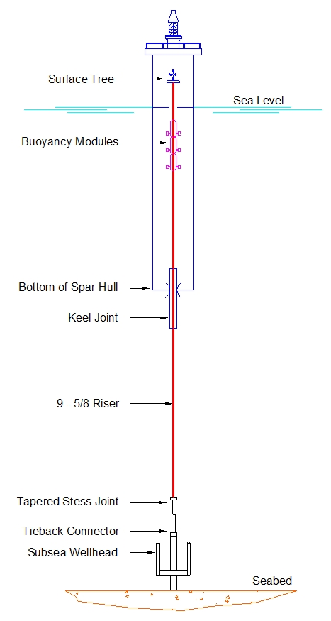
(see Figure 5.17, “Top tensioned riser applied to SPAR” and Section 5.3.2.2, “Top Tensioned riser applied to TLP and SPAR”)
The Neptune Field development was the first SPAR-based floating production system using multiple top tensioned production risers from seafloor wellheads back to the surface trees in the Gulf of Mexico at a water depth of 580m.
Rigid risers act as tensioned beams. To avoid buckling under its own weight, and excessive bending stresses under lateral wave, current and vortex shedding loads, the riser is tensioned.
In a TLP, there is still a small amount of movement of the risers and platform. Its riser system uses simple tensioning system composed of hydraulic cylinders. In the case of the SPAR buoy, there are still considerable vertical movements and buoyancy cans are used instead of the cylinders, taking advantage of the deep draft of the SPAR hull, which protects the buoyancy cans against the waves/current action. In both cases, flexible jumper pipes are used to link the trees to the fixed piping of the platform.
The following of the section will consider this more complex top tensioned riser applied to SPAR.
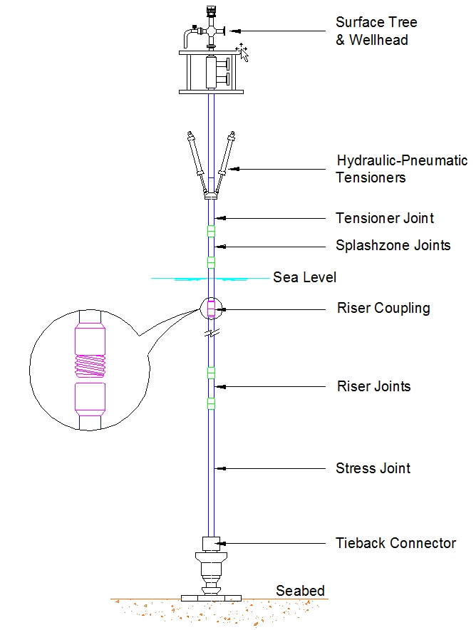
– Top tensioned riser applied to TLP
In this configuration, the riser system provides a pressure-contained link between surface tree and seafloor wellhead system. Each riser system acts as an extension of the well's production casing string providing primary pressure containment during well maintenance and work-over operations and secondary pressure containment during routine production.
The production riser system provides guidance for downhole equipment and various maintenance and stimulation activities associated equipment. Each riser has an internal diameter compatible with the well's production casing. Well production, gas lift/annulus access and downhole control are through dual tubing strings and umbilical lines within the riser.
riser installation uses casing installation equipment and techniques. Component assembly during installation is limited to make up of threaded-and-coupled connections. The few flanged connections within the string are pre-assembled and tested on shore.
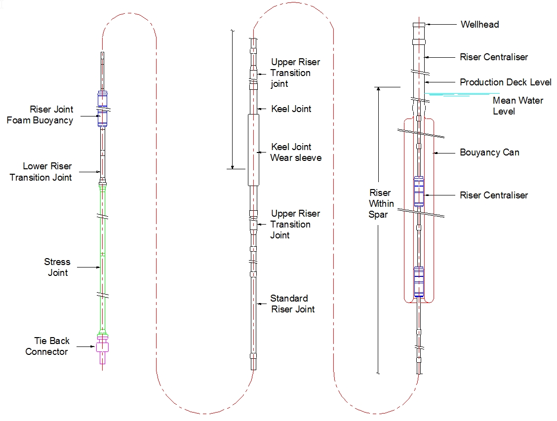
The SPAR production riser system consists of the following main components (see Figure 5.19, “– Detailed description of Neptune SPAR production riser”):
|
Functionalities of these components are described below:
Buoyancy cans
Each riser is independently tensioned by long buoyancy cans (which volume depends on the riser submerge weight). Stem from the upper can extends upward to the underside of the surface wellhead providing riser support. The lower two cans can be either flooded with water or displaced with air through two service lines running back to the production deck. The cans are fabricated in steel structures and lowered into the SPAR well slot as a single assembly using a crane barge. The buoyancy cans are sized to support the riser, surface wellhead, tubing strings, and tree.
Adjustable riser support structure
The adjustable riser support structure is a tool temporarily used to support a riser when weight increases are anticipated and at the same time allowing vertical adjustment to prevent riser over tensioning. If environmental conditions worsen to the point where allowable motions may be exceeded, the riser is lowered into a controlled buckled configuration and supported by the adjustable riser support structure. This prevents riser over-tensioning that might result from increased displacements of the SPAR.
Tieback connector
The tieback connector is the lowermost component in the production riser string and is part of a riser subassembly that includes a Titanium stress joint and lower riser transition joint. By making theses items a subassembly, critical flanged connections are made up and fully pressure tested before they are shipped offshore.
The tieback connector is remotely locked through an ROV hot stab to the wellhead housing, forming a pre-load structural connection and pressure containing interface with a through bore.
At the upper end of the tieback connector, a compact flange with beryllium-copper radial interference seal forms the load and pressure containing attachment to the stress joint.
Titanium stress joint
The use of Titanium stress joint reduces stresses in the riser and bending moments applied to the tieback connector due to its flexibility. This is especially critical during lateral offsets for the drilling operations. The stress joint is made from a high strength alloy, Ti-6A1-4V ELI.
The Titanium stress joint consists of cylindrical tubes. The two tubes with different OD are welded together and compact Ti flanges are welded to each end for connection to the steel flanges of interfacing components. The flanges incorporate radially energised metal-to-metal beryllium-copper seals. To prevent deleterious galvanic corrosion between the Titanium and steel, each steel flange is Inconel 625 overlaid. All the outer surfaces of the stress joint, plus the two flange connections are encapsulated in an elastomeric coating to prevent hydrogen absorption by the Ti and mitigate galvanic interaction between Ti and steel.
The lower riser transition joint is the uppermost part of the bottom subassembly and forms the pressure containing and structural crossover between the Titanium stress joint and production riser string. The upper connection to the riser string is a threaded-and coupled TCII. For corrosion protection, the outer surfaces are coated with thermal sprayed aluminium.
Riser joints
The bottom 3 riser joints have syntactic foam buoyancy modules. If a riser undergoing work-over operations is lowered on the adjustable riser support structure and supported by the SPAR, its lower end goes into a controlled buckled configuration. The buoyancy modules provide additional lift reducing the curvature in this area of the riser. The syntactic foam, sized so it easily passes the buoyancy cans, is attached around standard riser joints and vertically restrained by thrust collars.
The riser strings use TCII threaded-and-coupled connections. This connection creates a joint efficiency approaching that of L80 pipe in tension and compression with radially energized metal-to-metal seal.
The use of threaded-and-coupled connection allows the use of conventional casing string installation techniques and equipment.
For corrosion protection, the riser's outer surface is coated with thermal-sprayed aluminium. The coating acts as a combination barrier coating and cathodic protection system.
Keel joint
The keel joint provides a pressure containing conduit, hull to riser wear surface, and a reaction point for load transfer between the riser and SPAR. The keel joint prevents detrimental wear using a wear sleeve that rides within a bushing at the keel of the SPAR. The wear sleeve is attached to and supported by the inner pipe with a elastomeric bearing at each end.
Lateral loads between the SPAR and riser cause localized bending and the much-stiffer wear sleeve limits the inner pipe deflection by distributing the load through the elastomeric bearings and allowing the inner pipe to deflect into a curved configuration.
The keel joint is also a threaded end coupled joint. Because of the pipe size differences, transition joints are used above and below the keel joint to crossover to the riser string.
Centralising riser joints
Above the keel joint and inside the hull the riser is made of standard casing. As the riser comes up through the hull, it enters the buoyancy cans where it is laterally supported by centralising riser joints.
The centralisers are standard riser joints with neutrally buoyant 3m long syntactic foam modules. Like the buoyant riser joints, these foam modules are pre-installed on a standard riser joint and vertically restrained by thrust collar assemblies.
Three centraliser joints are added into the riser string positioned near the bottom, centre and top of the buoyancy cans.
Waveform joint
The last joint within the riser string is a waveform joint that provides for riser space-out using adjustable slips in the surface wellhead. Once the riser is locked to the seafloor wellhead and tensioned, the proper wellhead is determined and the waveform slips are set.
The landing ring, which is previously attached to the buoyancy can stem is stroked upward using the adjustable riser support structure and attached to the surface wellhead. The remaining waveform joint above the wellhead is removed and a seal assembly installed. A clamp hub and seal pocket at the upper end of the wellhead is used for attachment of the tubing spool.
Tubing spool
A tubing spool is attached to the wellhead that provides an internal bowl for tubing hanger support, sealing and lock-down. The upper end of the tubing spool has a clamp hub for attachment of either the surface tree or blowouts preventer spool. The hanger supports dual CRA (corrosion resistant alloy) tubing strings that run through the riser and lock into a packer located below the seafloor wellhead. A control umbilical strapped to the tubing strings provides riser annulus dewatering, subsurface safety valve control, and chemical injection.
5.3.2.3 Steel Catenary Riser (SCR)
Steel Catenary riser is essentially an extension of the pipeline, suspended in a near-catenary shape from the platform to the seafloor (similar to the configuration depicted in Section 5.2.5.1, “"Free Hanging" configuration”).
The SCRs are composed of steel pipe sections welded end-to-end, terminating either at:
A taper stress joint. This solution is possible only on floaters featuring low motions, e.g. SPARs.
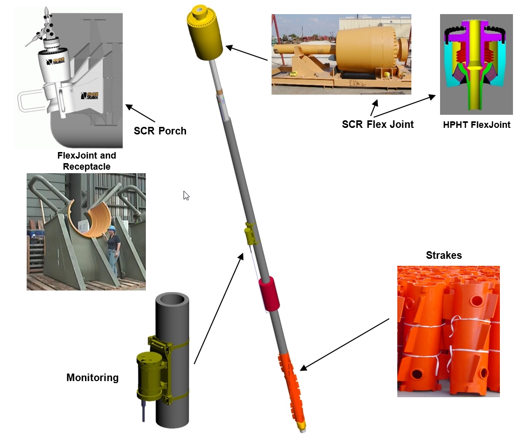
A flexible joint (e.g. on semi-submersible platforms), which is supported by a receptacle mounted on a support frame (see Figure 5.20, “Typcal SCR top section description”).
The entire riser has typically a triple coat epoxy/polyethylene coating for corrosion protection, thermal insulation coating if required. Abrasion resistant coating is generally used in the touchdown area.
The upper 150m have neoprene coating for additional protection and marine growth prevention, plus helical strakes for suppression of vortex induced vibration if required (see Section ).
The lower section of riser resting on the seabed could be anchored as required to minimise the horizontal displacement and to prevent excessive pull on connection point to Sealine when the floating production platform is in far position.
The Flexjoint technology (see Figure 5.20, “Typcal SCR top section description”) which accommodates the riser motions at the platform has made the steel catenary riser possible.
SCR have seen their merits in Gulf of Mexico, mainly in combination with TLP's and SPAR platforms. This type of riser in combination with semi-submersible platforms or FPSO is also being introduced in Gulf of Mexico, Offshore Brazil, and offshore West Africa.
The main current issues related to the SCR technology and design, are:
Integrity of the flex-joints
Wet insulation coating system capability.
Figure 5.21, “SCR insulation coating failure” below shows the wet insulation collapse during testing at hydrostatic pressure equivalent to 1200msw. The insulation consisted in a polyurethane matrix with large “mini-spheres” and hollow glass micro-spheres. The matrix softened at the service temperature bringing the spheres into contact causing premature collapse
Extended studies are performed on these subjects. However, the SCR is a field proven solution. A brief review of some of the key projects is presented below.
First SCRs were installed in 1993 on Shell’s Auger TLP in the Gulf of Mexico for oil and gas export. The SCRs were installed in a water depth of 870m using a flexjoint connected to the TLP pontoon, 20m below the mean water level. Their diameter and wall-thickness were 12” and 0.688” respectively. A J-lay installation method was used. For VIV suppression, 150m long helical strakes were used at the top portion of the risers. Since then similar SCRs have been installed on Shell’s TLP such as Mars (1x 14" and 1 x 18" in 950m WD in 1996), Brutus, Ursa, and Ram-Powell.
In 1997, the first SCR to a semi-submersible (Petrobras P18) was installed in the Marlim Field, Campos Basin offshore Brazil. The water depth was 610m. The SCR was part of a 10” gas import line with a wall-thickness of 0.812”. The material grade was X60 of API 5L. Because the dynamic motions were more severe, it was necessary to employ higher tension in the SCR, in order to reduce bending moments in the sag bend.
Following the trend of using steel catenary risers for export lines in Campos basin, Petrobras has installed 2 X 12" oil export SCR's on the semi-submersible P 19, at Marlim Field, in a water depth of 770 meters.
In 1998, Morpeth (in the Gulf of Mexico) export/import SCRs were installed on a TLP in a water depth of 520m. The J-lay method was used to install the straked portion of the riser and the rest of the riser was installed using the S-lay method.
In 2001, The Prince SCRs were installed on a TLP located in water depth of approximately 460m. The SCRs were part of two 12” oil and gas export lines. The SCRs have a departure angle of 24 degrees and a flexjoint angle variation of +/- 20 degrees to accommodate the TLP motions in such relatively shallow water.
The same year, the two 6” King Kong SCRs were installed in 2001 in 1000m of water, and suspended from Allegheny TLP. Buoyancies were required to reduce riser loads acting on the TLP. The SCR pipe wall-thickness is 0.791” and its material grade is API 5L X-65. Titanium stress joints of 8m were employed at the vessel interface. The external coating was fusion bonded epoxy, except 300m of touchdown zone where a three-layer polyethylene coating was used. 160m of strakes (type 5D) were installed below the stress joints.
In 2002, Typhoon 18” Gas Export riser has the lowest water depth to diameter ratio of any installed SCR to date, resulting in an extremely challenging fatigue design at the seabed touchdown point. The Typhoon TLP was located in approximately 650m water depth. Flexible risers were used for the production wells. A 10” oil export SCR and an 18” gas export SCR were used for product export.
8” and 10” Matterhorn export SCRs were, in 2003, the first reeled SCRs installed on a TLP, located in 870mwater depth. The design of these SCRs was one of the first to consider the Cold-Core Eddy Current (or submerged current) in the Gulf of Mexico. Reeled installation of the SCRs also affected the design, fabrication and fatigue testing process, particularly the pipe welding and matching process and the fatigue test and fracture mechanics analysis strategy.
The same year, the Na Kika SCRs were the first SCRs being designed and installed as pipe in pipe systems (by TECHNIP-FMC Deep Blue pipelay vessel). The SCRs were installed on a semi-submersible in water depth of approximately 1920m. The production SCRs were pipe in pipe systems while export SCRs were single walled.
Also, the Marco Polo 12-inch oil and 18-inch gas export SCRs were attached to a TLP located in 1300m water depth. During installation, one of the risers was shifted by about 250m toward the TLP. It was decided that four extra joints were to be welded to the SCRs, resulting in SCR departure angle change from 12 to 10 degrees.
In 2004, the Bonga SCRs (6 * 10", 3 * 12" in 900-1150m WD) were the first to be installed on an FPSO vessel (which has greater excursion than SPAR or TLP) offshore West of Africa. This is also the first time that corrosion resistant alloy clad pipes are used in a dynamic SCR application.
In 2005, Heerema Marine Contractors (HMC) has set a world record by the successful installation of steel catenary risers (SCR’s) onto the Mardi Gras Thunder Horse platform in the Gulf of Mexico. The installation of the SCR’s (20” and 24”) was executed in a water depth of 1,840 m and turned out to be the deepest 24” SCR ever installed. The SCR Campaign for the Mardi Gras Thunder Horse started initially in June 2005, but could not be completed then due to the ballast incident of the Thunder Horse platform in the Gulf of Mexico. This platform tilted in July 2005 following the passing of Hurricane Dennis after which HMC received a ‘service contract’ from BP.
In addition to the SCRs aforementioned, SCRs have also been designed for use on BP Atlantis in the Gulf of Mexico and the Erha FPSO and Akpo FPSO in the West of Africa.
In 2006 -2007, the seven deepest Production Flowline Steel Catenary risers (SCRs) have been connected via flexjoints to the Independence Hub Deep Draft Semi-Submersible located in Mississippi Canyon Block 920 (MC920) in 2 400 m water depth.
In 2014, as part of the ultra-deepwater (1780 m) field development of the Santos Basin, 300km offshore the Brazilian coast, 27 Steel Catenary risers (SCRs) with 3.9km each were successfully installed by Subsea 7, acting as a contractor for Petrobras These SCRs were the first reeled-CRA to be installed.
In 2015 and 2016 ,on Aasta Hansteen field , in Norvegian Sea, four 12” claded and 14” carbon steel SCRs have been installed in 1300 mWD under a SPAR platform.
For harsh environmental conditions, e.g. offshore Norway, the semi submersible platforms with flexible risers have during the last decades proved their excellence to deep water. However, as the developments in these areas now extend to even larger water depths, the SCR's is also becoming the desired option.
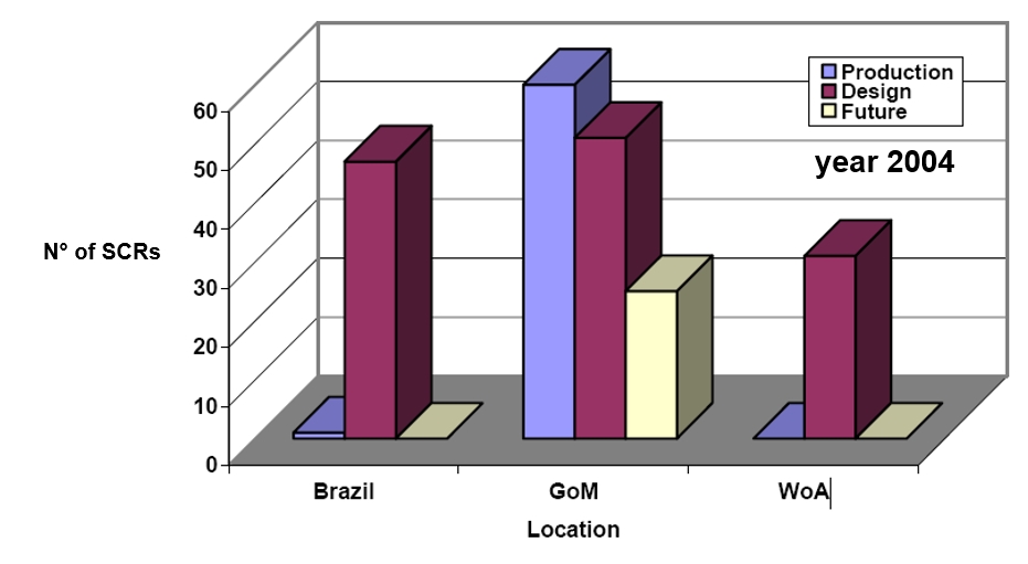
Statistics, illustrated in Figure 5.22, “Number of SCRs Installed/Proposed Worldwide (215)”, demonstrate the dramatic increase by showing that the number of SCRs currently either under design or planned exceeds the current worldwide inventory of operating SCRs.
5.3.2.4 Steel Lazy Wave Risers (SLWR).
The Caesar-Tonga development (Anardarko) in the Green Canyon Area in the Gulf of Mexico was the first application of steel lazy wave risers in the Gulf of Mexico, and it was the first such application tied back to a spar platform.
The Parque das Conchas (BC-10) project is located in deepwater, in block BC-10, off the coast of Brazil. It comprises a number of subsea fields tied back to a centrally located turret moored Floating Production Storage and Offloading (FPSO) host in some 1800 meters of water and connected via 7 Steel Lazy Wave Risers (SLWR).
5.4 Hybrid riser Systems
As an alternative to the previous riser systems, hybrid riser systems combining rigid and flexible pipes appear to be an attractive solution for deepwater applications.
Hybrid riser systems are developed in various configurations. The applications have been pioneered by the Grand Banks 388 installation in Gulf of Mexico and the Girassol (1350m WD) installation in West of Africa.
Two types of approaches to decouple the floating structure motions from a series of risers under harsh environmental conditions have been developed. Hybrid Riser Tower (HRT) and Hybrid 'S' riser (HySRTM). In the HRT system, a riser bundle in straight ‘tensioned’ configuration is supported by a buoyancy structure or distributed buoyancy elements, which provide excessive buoyancy to tension and stabilise the riser system. In the HySRTM solution, several SCRs are supported by a buoyant mid-water arch connected to seabed foundations by tethers. For both concepts, the risers are connected to the floating structure by flexible jumpers. Analyses confirm that with either concept, the fatigue damage due to FPSO vessel motions is significantly reduced and the compress-induced over-bending at hang-off and sag-bend no longer exist.
A derivative of the HRT solution is the Single Hybrid Riser, which is based on the same concept of a steel riser tensed by a subsea buoy and connected to the floater by flexible line, but which include one single line per riser rather than a bundle of lines..
| Tip Click these links below for access to 3D resources: |
The hybrid riser solution is now used on several fields, as follows:
1. Bundled riser towers/bundles:
Girassol (TOTAL), Angola (WOA), 1350m water depth. Three riser towers to include the ten 8” production risers, three water injection lines and two gas injection lines.
TOTAL Rosa field in Angola, 1300m. The risers will connect the subsea facilities to the Girassol FPSO.
Greater Plutonio (BP), Angola (WOA), 1300m water depth. One self-standing bundled riser tower encases three production risers to connect the 12” production lines to the FPSO via flexible pipes. The 1,200m long bundle is made of a core pipe wrapped with shells of syntactic foam for the tower’s buoyancy, with all 11 risers (including injection risers) fastened on the outside of the tower.
The CLOV development is located offshore Angola in a water depth of 1,300m and includes two Hybrid Riser Towers. The first oil was successfully achieved on June, 12 2014 as initially scheduled at project award in July 2010.
2. Single Hybrid Risers (SHRs):
Kizomba A and B (ExxonMobil), Angola (WoA), 1000m-1200m water depth. The two phases of the field feature the installation of four water injection SHR (10” and 12”), three 10” gas injection SHR and three production Pipe-in-pipe SHR (8”x11” and 12”x15”) also known as COR (Concentric Offset Riser).
The first Petrobras Hybrid riser was installed in Campos Basin and is part of the Roncador P-52 oil export system. This system, which connects the SS platform P-52 (1800m water depth) to the fixed unit PRA-1 (100m water depth), is in operation since November 2007 comprises an 18 in diameter Flowline and the Free Standing Hybrid riser (FSHR). The FSHR is composed by a grouted foundation, 1500m of rigid steel riser, a near surface Buoyancy Can and a flexible jumper connecting the top of rigid riser to the platform.
The development of the Usan field has involved 23 production wells and 19 water and gas injection wells connected to a two-million-barrel capacity floating production, storage and offloading (FPSO) vessel by subsea lines and Single Hybrid Risers.
The development of CLOV (Cravo Lirio Orquidea Violetta) has involved 34 wells and the SURF (subsea umbilical, risers and flowlines) element of the project required one Single Hybrid Riser for Gas Export, nearly 100 kilometres of infield flowlines plus a 32km gas export line (first oil 2014).
Located in 2 500 m water depth, the Cascade & Chinook subsea development hybrid Risers are one of the deepest production Risers in the world. These are also the first offset free-standing hybrid risers to be installed in the Gulf of Mexico, and the world's first use of hybrid Risers in combination with a disconnectable turret-moored FPSO (2011).
The development of the Kaombo Ultra-Deep Offshore Project (first oil in 2018) primarily involves the drilling of 59 subsea oil production wells, which will be connected via 300km of subsea lines and first oil in 2018Single Hydrid Risers to two floating production, storage and offloading (FPSO) vessels, named named Kaombo Norte and Kaombo Sul.
The development of EGINA Project (first oil in 2019), comprises 8 Single Hybrid Risers (4 for Production, 3 for water injection and 1 for Gas export).
5.4.1 Single Hybrid Riser & Riser Tower/bundle
The Single Hybrid Riser & Riser Tower/bundle system has two unique features:
Compliant reaction during the slow drift motion of the FPS,
Versatile concept as the main riser body (nearly neutrally buoyant) can be extended to any required water depth.
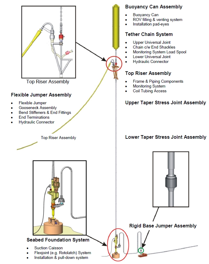
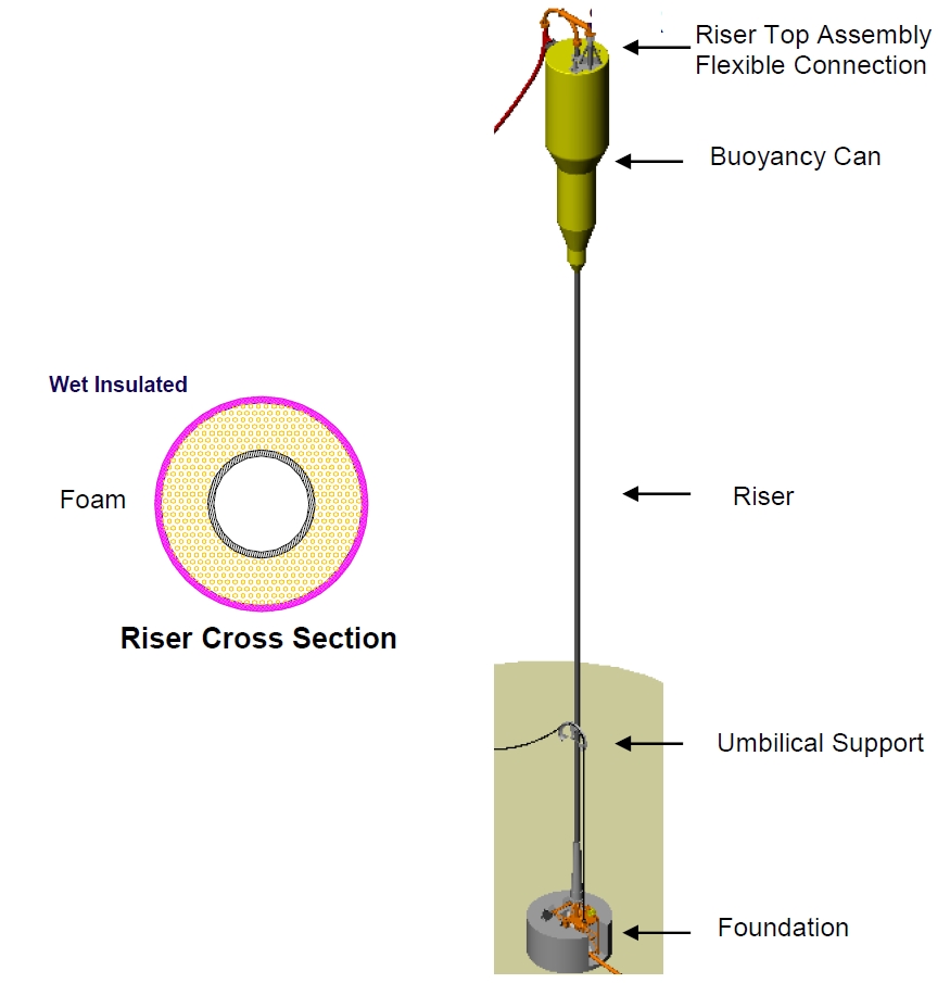
The concept of the ‘free standing hybrid riser’ (FSHR) includes the following main items (see Figure 5.23, “– Free Standing Hybrid riser Concept (Typical – Production Single Leg riser)”):
A riser base
A (single or bundled) riser tower
A subsea buoy
Flexible riser(s)
Riser Base
The structural response of a hybrid riser tower is highly dependent on the selected base tension, which typically ranges between 100 - 200Te for single line and pipe in pipe risers and 300 - 600Te for bundled risers. The base tension is reacted at the seabed via a foundation. A number of foundation options are possible:
Driven piles (Placid Green Canyon, Garden Bank)
Suction pile (Girassol, Kizomba A and B, Block 18 (planned))
Drilled and grouted piles ( Petrobras P52 (planned))
Gravity base
Jetted pile
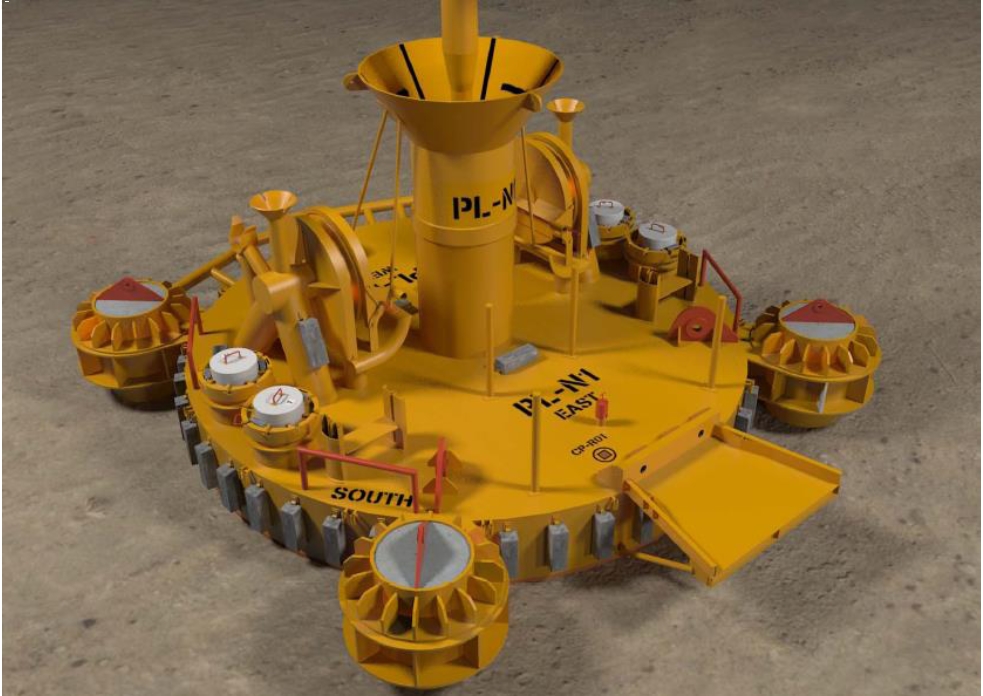
The riser base also includes a connection system to latch the riser tower. The transition between the riser and the foundation can be either fixed or pinned.
In case of fixed transition (mandrel connector for Petrobras P52, collet connector, etc.), the bottom riser is rigidly fixed to the foundation thereby preventing any rotation of the riser relative to the foundation. This approach is similar to that used on top tensioned SPAR and TLP production risers. This arrangement generating high bending moments at the interface between the base of the riser and the foundation, the bottom riser is reinforced by steel or even titanium taper Joint (see Figure 5.24, “- Fixed transition between the bottom riser and the foundation”). The main advantage of this arrangement is that it eliminates a high proportion of the relative movement between the riser and the Flowline termination simplifying the rigid jumper design.
In case of a pinned connection, the rotation between the bottom assembly of the riser and the foundation may be ensured by an anchor latch system incorporating an elastomeric joint (e.g. Girassol, which features a Rotolatch system, and Kizomba A and B )
The main disadvantage of this pinned connection is its impact on the design of the rigid base jumpers which must be able to accommodate the angle variation between the riser and Flowline termination. This leads to large spools with multiple bends to achieve the necessary degree of flexibility.

Flexible or rigid jumpers allow the connection of the Sealines to the lines contained within the riser tower.
Single Hybrid Riser & Riser Tower/bundle
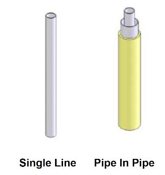
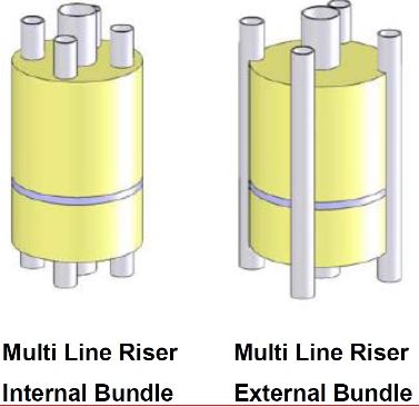
A riser tower rises from the riser base to the bottom of a subsea buoy located below the sea level (in order to mitigate the current-waves action on the subsea buoy). The riser tower can be either single pipe, pipe in pipe or a bundle of pipes (Flowlines, injection and service lines, heating lines, etc.) configured in either an internal or external bundle configuration.
Syntactic foam modules ensure additional uplift forces (to the main subsea buoy) and could also provide thermal insulation of the riser bundle.
Subsea Buoy
The subsea buoy provides the main uplift force to the riser tower in order to improve the dynamic behaviour and keep the riser tower in tension whatever are the environmental conditions. The subsea buoy top can be located between 50m–200m below the sea level (depending on system natural period and environmental loads) in order to minimise the influence of surface current and waves.
As shown on Figure 5.28, “Girassol Top Buoyancy Can” and Figure 5.29, “Greater Plutonio Top Buoyancy Can”, the buoyancy tank may include a support balcony for the flexible risers and gooseneck spools to ensure flow continuity. In this configuration, pipes pass through the buoyancy tank.
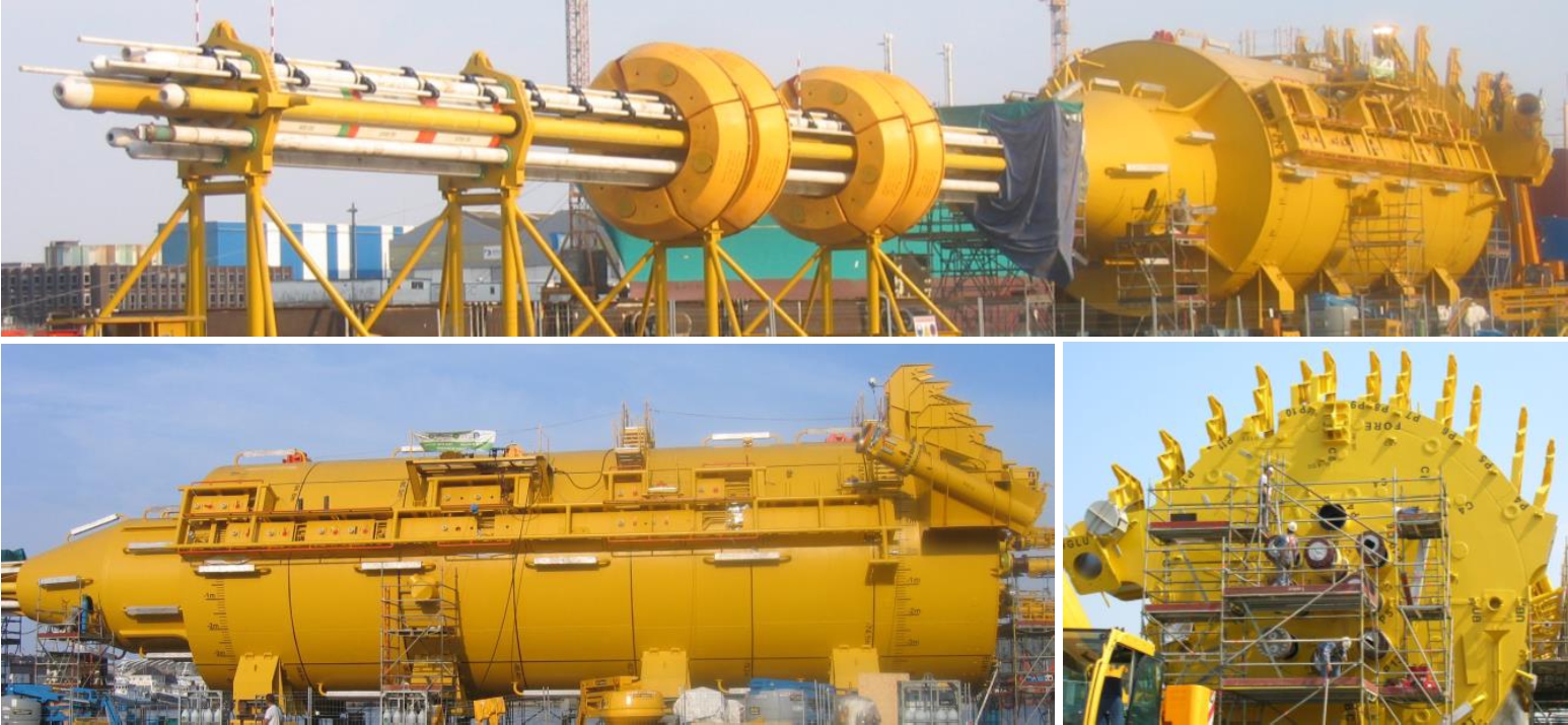
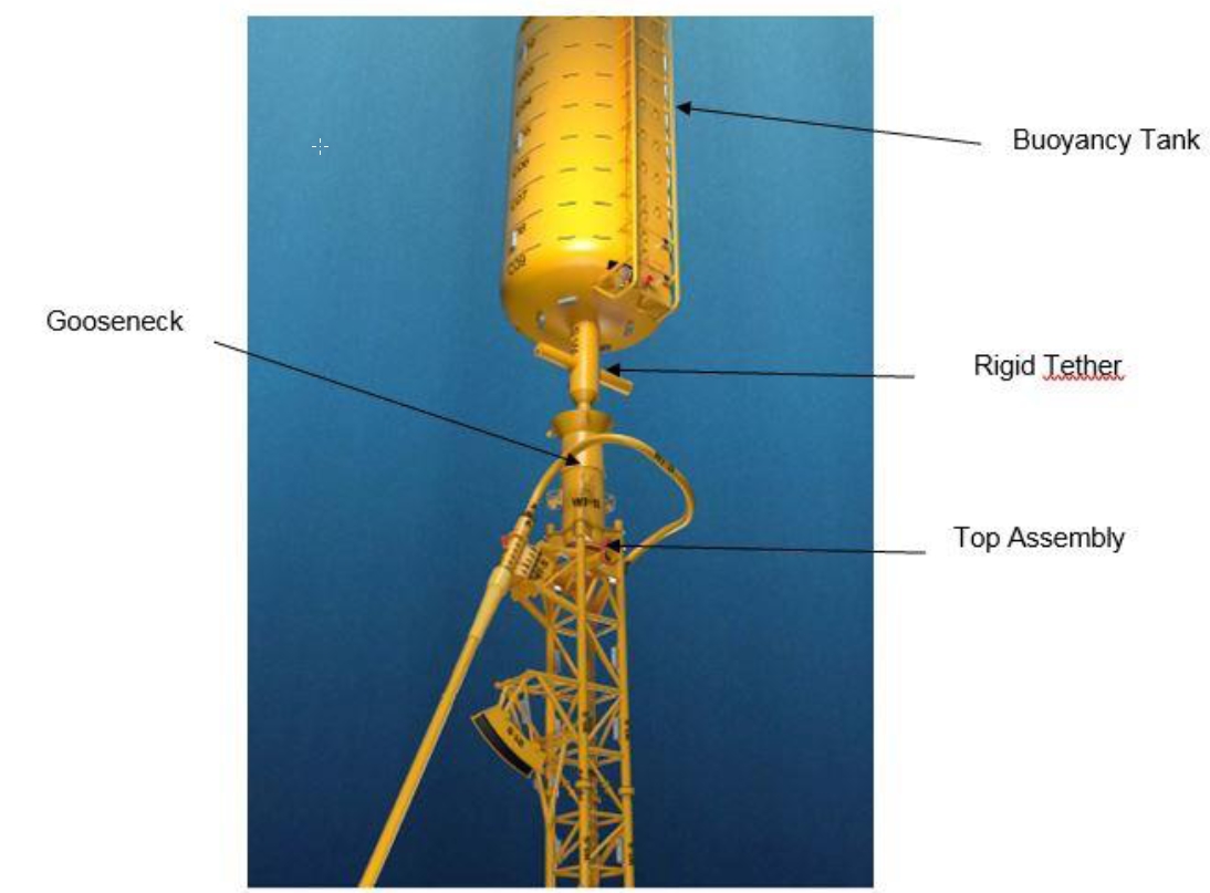
In some applications especially in the case of a single line riser, the flexible pipe does not connect the top of the buoyancy can but is linked to a riser top assembly connected by a chain tether at the bottom of the buoyancy can. As shown on Figure 5.30, “- Buoyancy tanks linked to the top riser by a chain”, a tether chain links the top of the riser to the buoyancy can while a gooseneck supported by a top assembly connects the vertical rigid riser to the flexible jumper.
The compartments of the buoyancy tank are filled and slightly over-pressurized to ambient hydrostatic pressure with nitrogen.
Flexible riser
Flexible risers connect the tower top assembly to the FPS while allowing relative motions. However, flexible jumpers have several limitations on diameter, temperature, pressure, and service life.
Different types of hybrid riser towers are presented below.
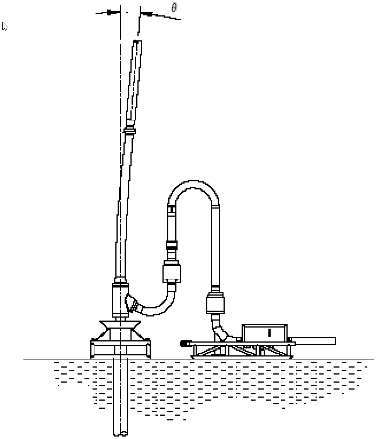
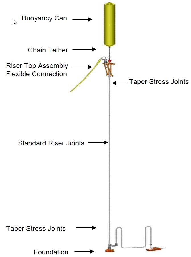
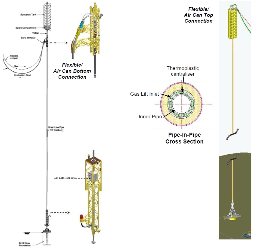
5.4.1.1 Single Hybrid Riser
A single line hybrid riser is depicted on Figure 5.31, “Single line hybrid riser”.
This type of hybrid riser (featuring one line) is installed on Kizomba A and B for water and gas injection lines. These single leg hybrid risers (SLHRs) are the first application of this concept.
The 18”oil export riser for Petrobras P-52 submersible platform (Roncador 1800m) is a free standing hybrid riser (FSHR) connect to an 18” oil export pipeline system (to shore), is illustrated in Figure 5.32, “- Free standing hybrid riser: 18”oil export riser on Petrobras P52”.
5.4.1.2 Pipe-in-Pipe Hybrid riser
The Pipe in Pipe Hybrid riser concept is a freestanding hybrid riser arrangement, which consists of a vertical rigid pipe in pipe anchored to the seabed and tensioned by means of an air can. The connection with the floater is performed either by means of two flexible jumpers or by an IPB which integrates the production and gas lift lines. The pipe in pipe design provides additional insulation and allows riser base gas lift and active heating through the annulus.
Single Pipe in Pipe hybrid risers are being used for subsea production wells on Kizomba B.
Figure 5.33, “Pipe in Pipe Hybrid Risers general arrangements” presents two typical systems of pipe in pipe hybrid risers.
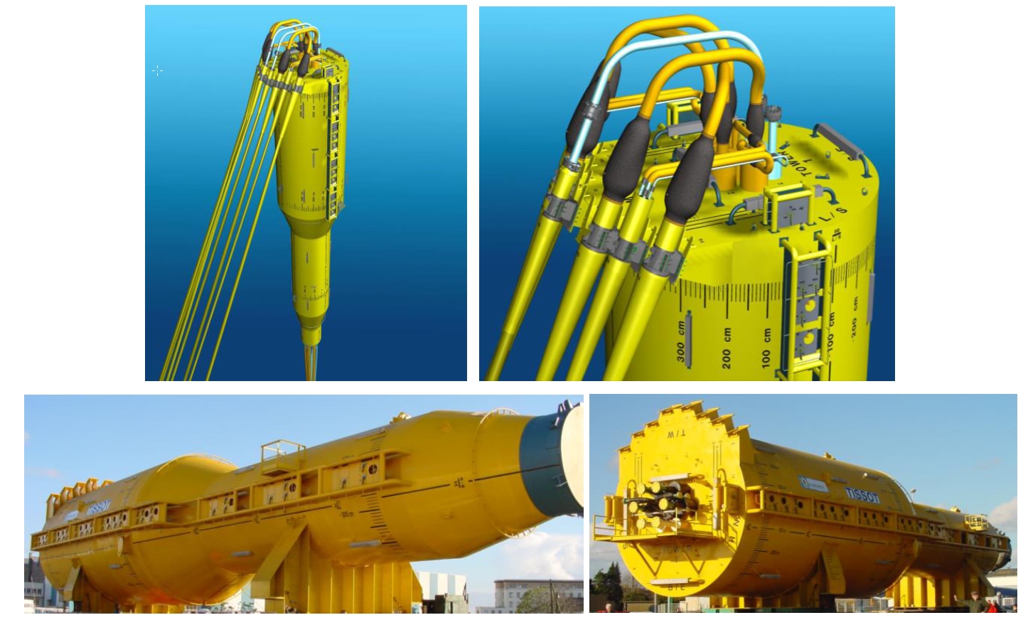
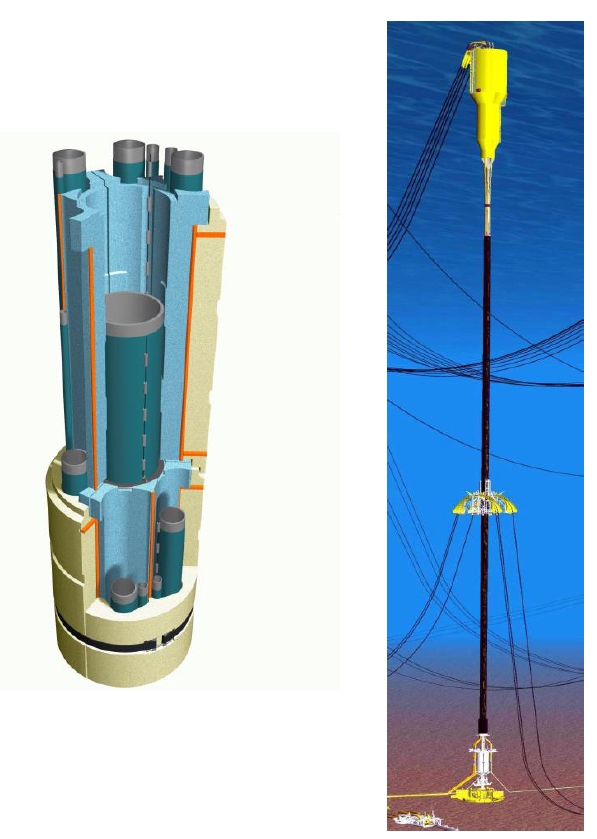
5.4.1.3 Multi Line Hybrid riser
Three (3) multi line hybrid riser towers located to the east of the Girassol FPSO are in production. In each tower six identical riser lines for production and injection are integrated.
Each riser tower is 1288 meters long from the sea bottom to 50 m below the sea surface and is divided in three main sections:
Buoyancy tank including taper joint. It provides require tension for the Riser tower compliance requirement.
riser bundle with a 22” OD central core pipe around which production, injection, service and gas lift pipes are positioned.
Bottom part including the Riser base foundation. The central core pipe is connected to a suction anchor through a bottom flex-joint, which allows angular displacements of the riser tower.
Since the three ‘Girassol’ riser towers; two other riser towers (to FPSO) will be installed in Angola, i.e. Rosa Lirio and Greater Plutonio.
5.4.1.4 Other concepts
Other concepts of riser towers have been studied at conceptual stage:
Each of these concepts is briefly presented below:
|
|
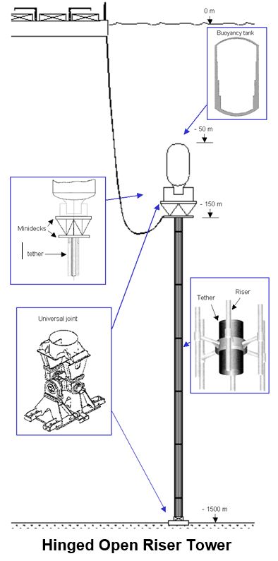
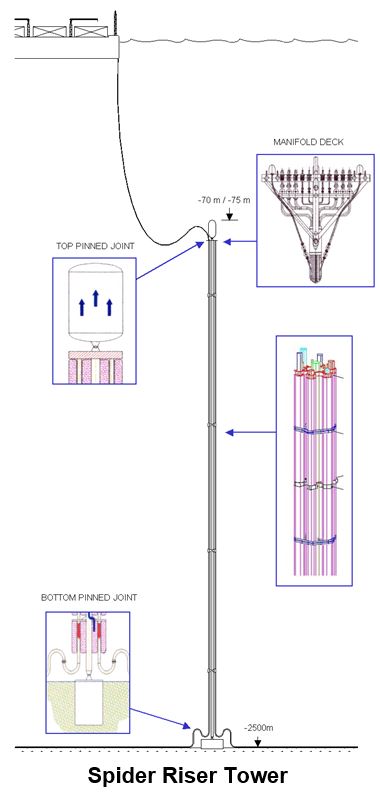
Hinged Open riser Tower This concept comprises a main structural tether around which are fitted production lines. It is suspended from a buoyancy can which gives the necessary top-tensioned. The particularity of this concept is the connection between the tether and the buoy and between the tether and the anchor. It is obtained by means of a double-swivel junction (universal-joint type). One of the driving principles of the HORT concept lies on the mechanical independence of the riser and tether section, and of the top tensioning system. | Spider riser Tower This concept is suitable for an application down to 2500 m of water. The spider cross section supports the individual risers around a central structural core pipe by a series of regularly spaced riser guides. The tower is anchored to the seabed by a riser base system and a discreet buoyancy tank is attached to the top of the tower to provide the necessary in-place buoyancy. |
|
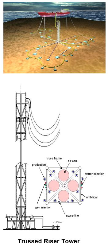
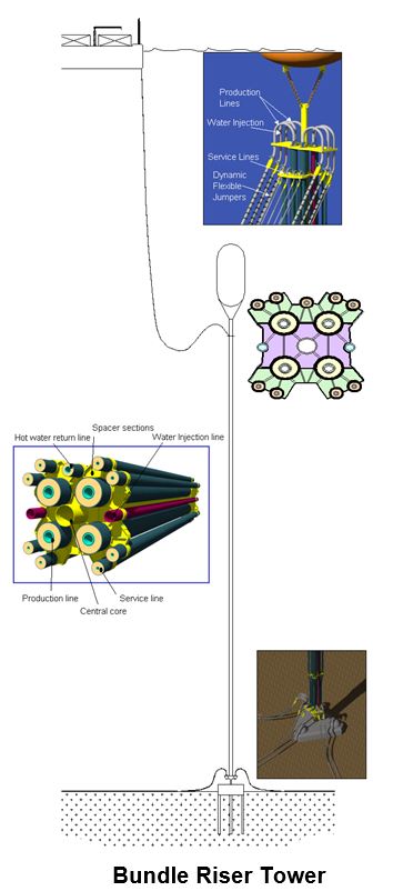
|
Trussed riser Tower The truss concept (based on the SPAR design) was developed during the design competition for Dalia development (Angola Block 17). The riser gather all riser elements in one envelope, that contains and supports a vertical array of all production, injection risers, umbilical, service lines, etc, between the sea-flour and a transition point near the sea-surface where flexible jumpers connect to the floating production vessel. | Bundle riser Tower Bundle riser tower has individual riser maintained around a central structural core by spacer sections. It is anchored to the seabed by a riser base system and a buoyancy tank is attached to the top of the tower. |
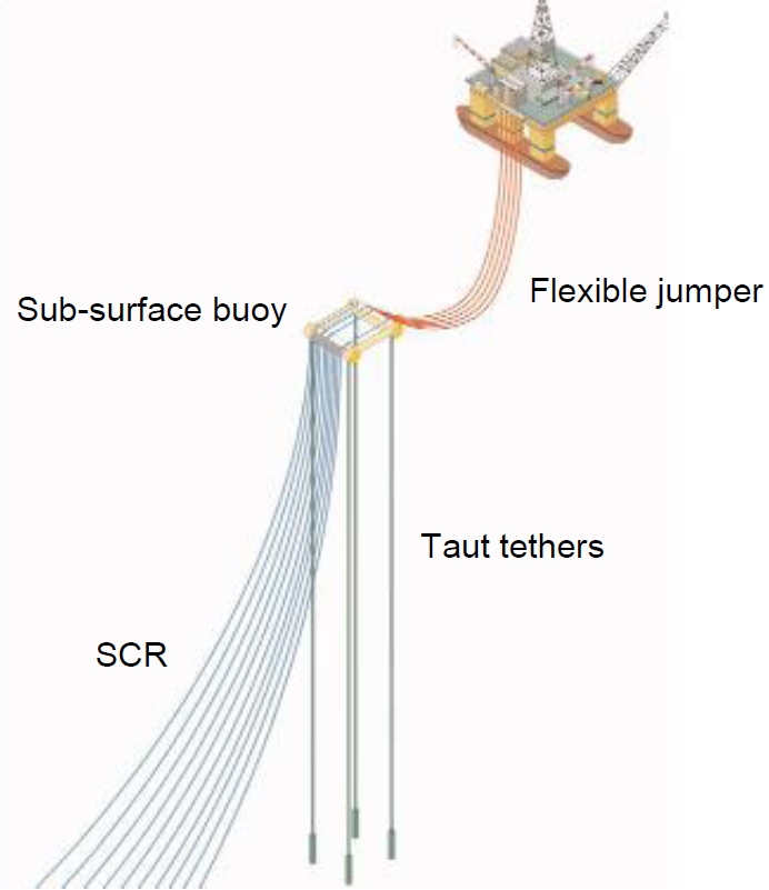
5.4.2 Sub-surface Buoy Systems
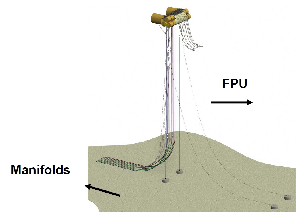
The hybrid riser concept based on sub-surface buoy combines flexible risers and steel catenary risers supported by a buoyant subsea arch, which is anchored to the seabed by taut tethers to limit excursions (Figure 5.35, “- HySRTM System General Configuration”).
The system includes the following concepts:
The Buoy Supported Riser (BSR) system, developed by Subsea 7 for Petrobras Guara-lula project (Petrobas).
• The Tethered Catenary Riser (TCR) concept, developed by Subsea 7
The Hybrid ‘S’ riser (HySRTM) concept (Figure 5.35, “- HySRTM System General Configuration”), developed by SEAL Engineering (TECHNIP-FMC Group) has been designed and tested for West of Africa and Brazil deepwater applications (1250m and 1800m water depth respectively) respectively for 7 and 14 SCRs.
The solution developed by Petrobras (Figure 5.38, “- BSR System”), which features a sub-surface buoy ‘four’ points anchoring system.
The HySRTM riser system consists of the following basic components described below.
Subsea arch
The subsea arch (Figure 5.36, “- Subsea Arch”) key function is to support the different risers while allowing FPU motion decoupling. It is composed of the following main elements.

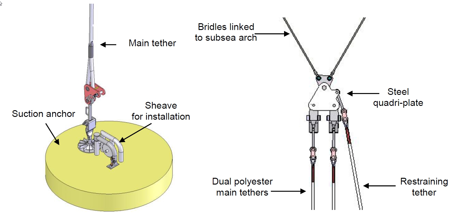
Tethers and Foundations
Two tether and foundation systems anchor the subsea arch to the seabed. Each tether-foundation system is made up of the following main elements:
Steel quadri -plates with two tie-rods connected to the subsea arch.
Dual polyester (or steel) main tethers (for redundancy and safety) transmitting the buoy net uplift tension to the foundation. The tether material depends on the field (meteocean conditions, subsea arch size and uplift..)
A restraining tether (anchored at seabed by pile) whose restoring force counteracts any overturning moments induced by the SCR tensions at the subsea arch.
A suction anchor: Only one main tether connection system is represented for clarity purpose in Figure 5.37, “- Tethers and foundation system”.
Steel catenary risers
Steel catenary risers capable of transporting fluids between the seabed Flowlines and the subsea arch are attached on the subsea buoy hang-offs.
Flexible jumpers
Flexible riser jumpers are used to transport fluids between the subsea arch and the FPU.
Another concept has been studied by Petrobras. The BSR system (Figure 5.38, “- BSR System”) requires a Sub -Surface Buoy that is moored on the sea bottom by taut tether systems on the four corners of the rectangular-shaped buoy. From the platform to the SSB the flow goes through a flexible riser while from the SSB to the sea bottom, the production flows through steel catenary risers (SCR).
This system was firstly developed in Deepstar JIP, coordinated by Texaco in 1996/1997. The buoy had an H shape, where the risers were installed in the central bracing of the structure. Petrobras performed several structural analyses and concluded that this solution is feasible to use in deep water fields. Due to the fact that H shape using 4 SCR had interference with the tethers, a new shape was design and the rectangular ring was chosen to be the best solution, in 1998. During the period 2000/2001, a new buoy was designed for 12 SCRs (Albacora Field case). Finally, this concept was extended to 1800 m water depth, sustaining 19 risers, during the years 2002/2003.
The Caesar-Tonga development (Anardarko) in the Green Canyon Area in the Gulf of Mexico was the first application of steel lazy wave risers in the Gulf of Mexico, and it was the first such application tied back to a SPAR platform.
The Parque das Conchas (BC-10) project is located in deepwater, in block BC-10, off the coast of Brazil. It comprises a number of subsea fields tied back to a centrally located turret moored Floating Production Storage and Offloading (FPSO) host in some 1800 meters of water and connected via 7 Steel Lazy Wave risers (SLWR)


