
9 Vortex Induced Motion (VIM)
9.1 General
Whereas VIV is normally associated with tall cylindrical bodies, VIM is used to refer to the motion of bigger elements, such as SPARs production floaters or hybrid riser subsea buoy.
Vortex Induced Motion (VIM) is a known problem for SPAR platforms and deep draught semi-submersibles under current conditions. The existence of the VIM of buoyancy can of a hybrid riser system is also demonstrated. Such VIM has implications for the fatigue life of riser pipe (in case of a riser tower) or SCRs which are attached to the buoyancy can (in case of an hybrid "S" riser ) or to a SPAR. Due to the potential impact of VIM on riser string or SCRs, and its top assembly structure fatigue life, it is imperative that this issue be properly addressed in riser system design and analysis.
Fatigue damage generated from VIM fatigue analysis has to be appropriately combined with other damage such as riser VIV, installation and wave induced fatigue to get the total fatigue damage of the system.
9.2 VIM Prediction
The VIM responses of a buoyancy tank can be evaluated by combining:
a theoretical approach
a finite element program such as Flexcom/Modes 3D
a code analysis (DnV)
If the calculated fatigue damage from this VIM estimation cannot satisfy the design criteria, it is recommended to perform:
scaled tests
in-field tests
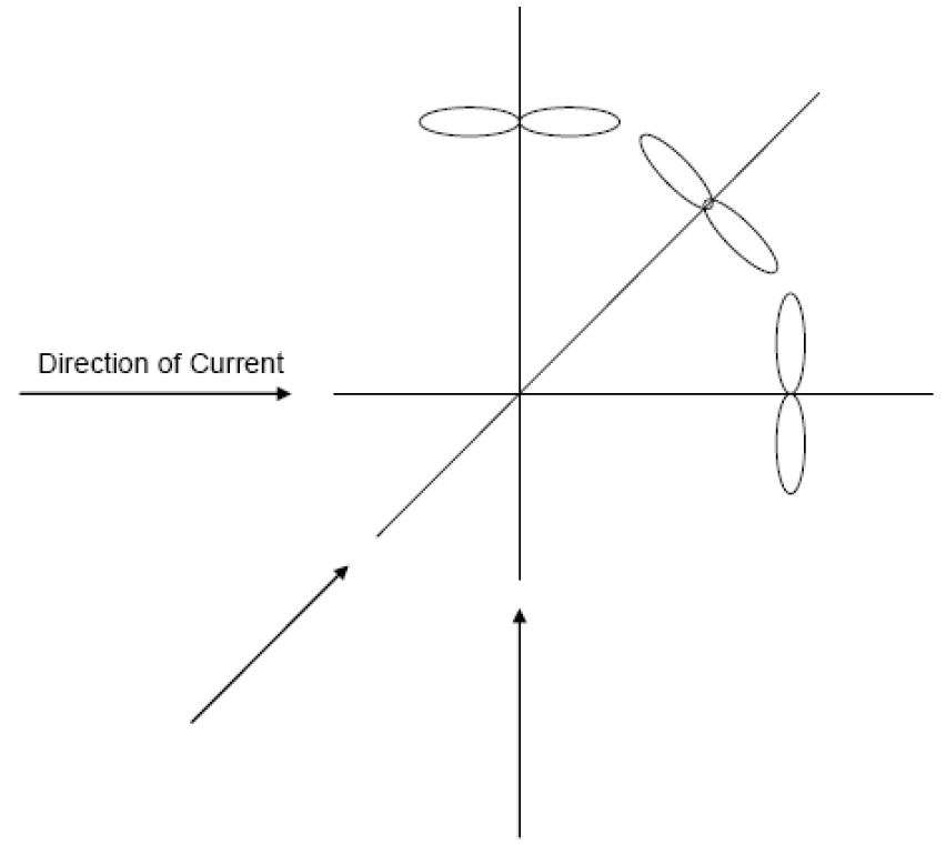
The primary motion of a buoyancy can or a SPAR under current is perpendicular or transverse to the current directions, while the secondary motion is in-line with the current. Together, these trace a “figure eight” in the horizontal plane. The phenomenon is illustrated in ???.
Transverse (Cross Flow) VIM
Transverse VIM occurs when the vortex-shedding period is close to the natural period of the buoyancy can or the SPAR. It takes place in the direction perpendicular to the current following closely a sinusoidal pattern. Transverse A/D is normally defined as the ratio of single amplitude to the buoyancy can diameter or SPAR diameter.
In-line VIM
In-line VIM occurs in the direction of the current, and it is affected by the transverse VIM. The magnitude of in-line A/D is typically 10% to 25% of the transverse A/D. However, inline motion is mainly at twice the frequency of the cross-flow motion. Thus, in general, the fatigue damage contributed from in-line VIM can not be negligible.
VIM is a function of a number of parameters:
Reduced velocity (depending of the current velocity, the buoyancy can or floater natural period and diameter). Model test data indicate that VIM amplitude is a function of the reduced velocity (Vr), and VIM is negligible when Vr is below a threshold value.
Current characteristics (profile, turbulence, velocity, and direction),
SPAR type (classic or truss) and hull appurtenances in case of a SPAR system
Buoyancy can shape (diameter and length) and flexible attachment system in case of hybrid riser tower. Note that some experiments have shown that an optimum buoy configuration for each specific current velocity should exist in order to minimize the vortex shedding effect in the large motion on the transverse direction.
riser content: it influences the axial tension of the riser consequently the stiffness of the system.
Hydrodynamic coefficients (added mass and drag coefficient) of the system.
In general for SCR, attached to a SPAR, the locations of primary interest are the hang-off and touch-down regions.
For a riser tower system, it is the connections of its end that needs special care. As it is at the extremity of the riser that buoyancy can VIM acts, a convenient application of stress joints or flexible joints on both riser ends would improve riser service life..
9.3 Suppression Devices
If potential VIM effects are detected during the engineering phase of the hybrid riser system, one of the two following solutions may be used:
Either redesign the buoyancy can or the riser by modifying the tension, changing its mass or designing another configuration. This solution is generally costly.
Or add some helical strakes on the air can or SPAR.


