
12 Monitoring Devices for risers
12.1 Monitoring of flexible risers
Flexible pipe monitoring and inspection systems consist of:
Polymer monitoring: online, offline, top side or subsea. Two monitoring techniques to determine the ageing of a PA11 internal pressure sheath exist, the polymer coupon sampling and the FDEMS.
Annulus monitoring: The integrity of the annulus of a flexible pipe, i.e. the space between the pressure sheath and the external polymer layer, is important to monitor from a service life, safety and environmental point of view. Three integrity measures are being utilised : annulus gas sampling (used to determine the corrosiveness of the annulus environment), annulus vent rate monitoring (it measures total volume and rate of a vented gas and then can monitor a seawater ingress) and annulus vacuum or nitrogen testing (to determine whether the annulus can hold a vacuum i.e. the integrity of the external sheath).
Steel armour inspection: two methods can be used to inspect the steel armour layers in a flexible pipe, the external Eddy current inspection (pass an alternate current magnetic field through the external polymer coating and monitor the eddy currents set up by the tensile armour wires), and the external radiography (radiography can detect density changes in a material through variations in the absorption of X-rays and g-rays)
riser dynamics: tension, angle and curvature
Internal fluid temperature and pressure
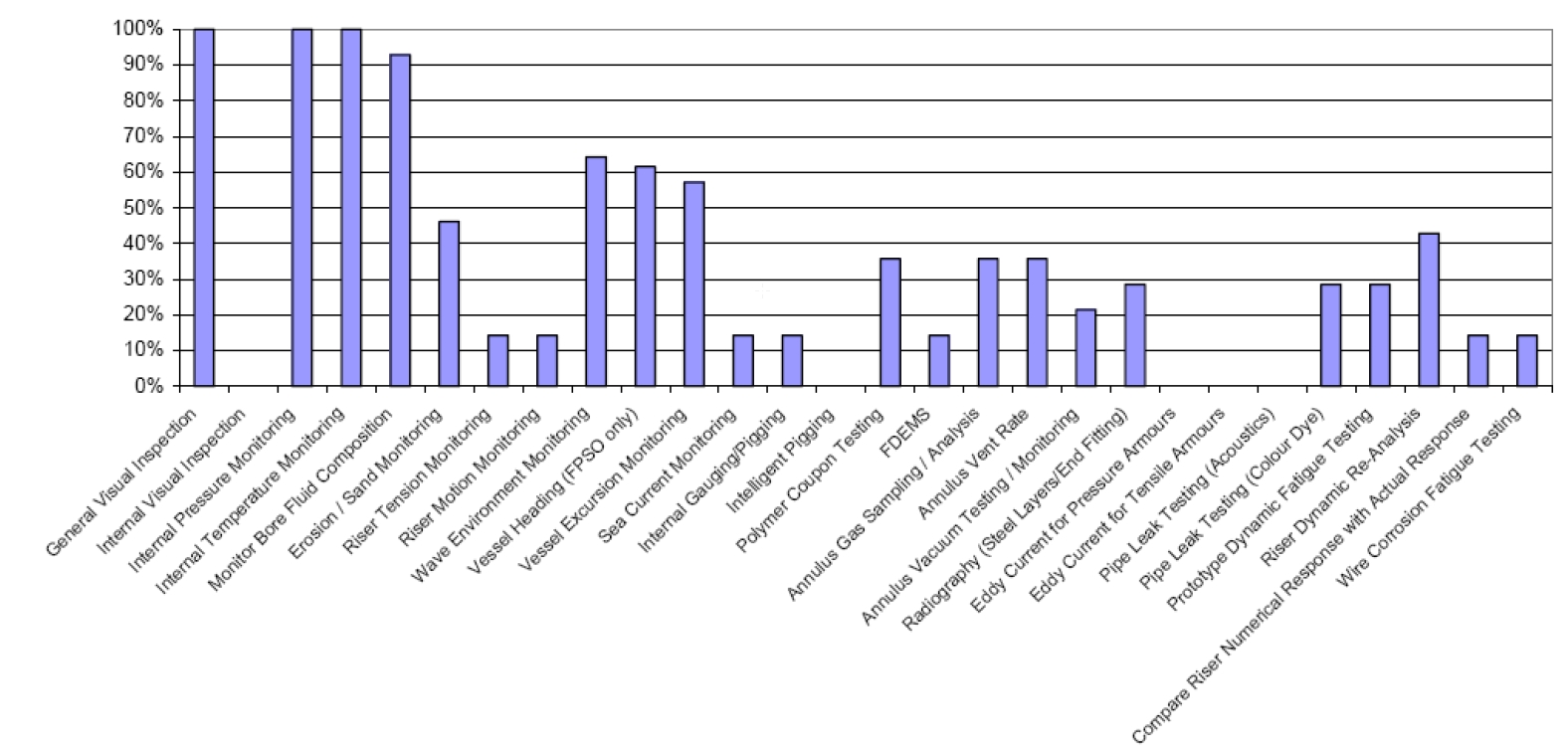
The following figure shows a statistical study concerning the inspection and monitoring analysis technique used for flexible pipe.
12.2 Monitoring of rigid risers
Rigid risers (especially SCRs) need to be extensively monitored to track the calculated fatigue damage at critical locations on the riser specifically at the touch down zone and the hang-off locations. A typical arrangement is shown in Figure 12.2, “Steel Catenary riser Monitoring”.
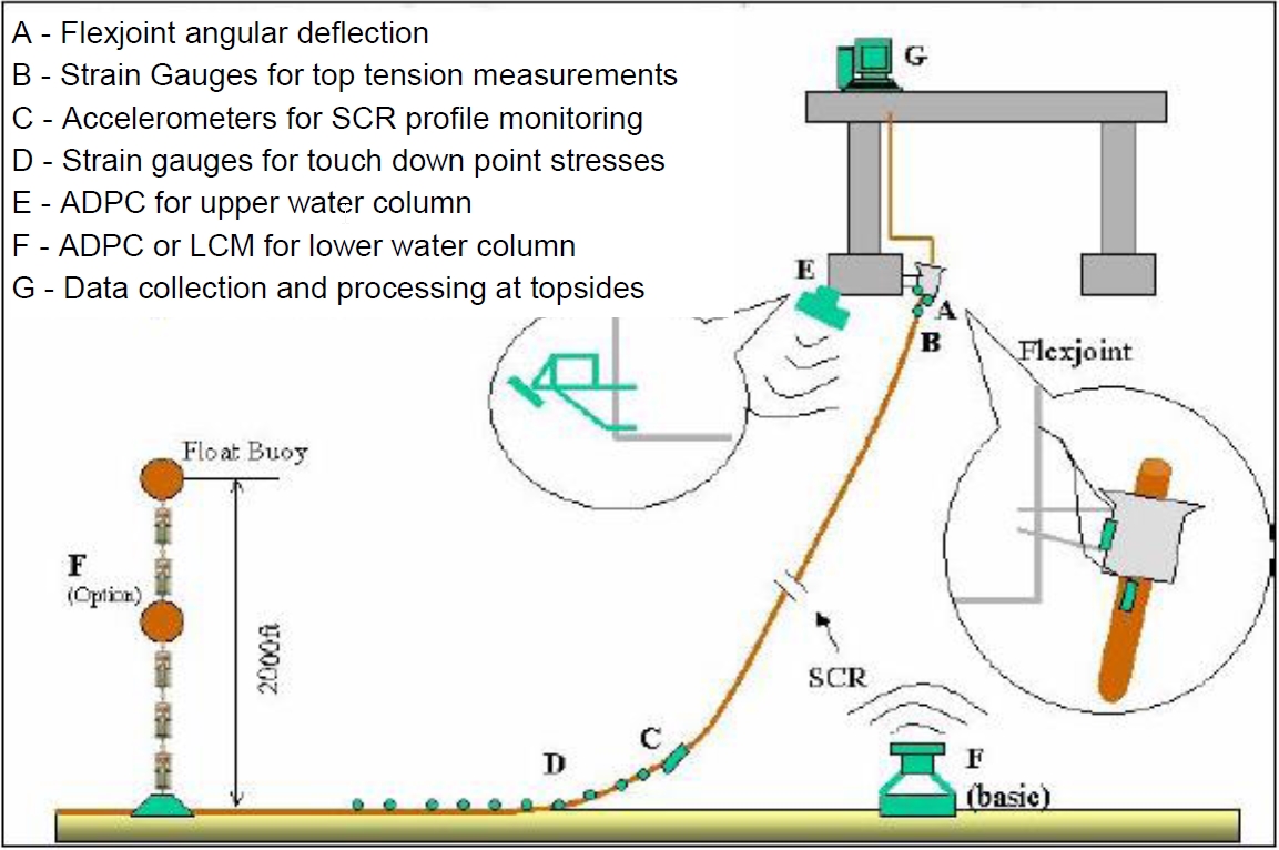
As shown in Figure 12.2, “Steel Catenary riser Monitoring”, the monitoring locations on a SCR are:
SCR Top:
Monitoring angular deflection of flexjoint or tapered stress joint using inclinometer.
Monitoring riser top tension using strain gauge.
Monitoring riser strain using a series of strain gauges.
Monitoring riser profile using one accelerometer just above TDP.
Current Profile:
Strain gauges, accelerometers, pressure and temperature measurement devices, applicable for rigid risers are depicted in the following section Section 12.3, “Monitoring of hybrid riser tower”.
12.3 Monitoring of hybrid riser tower
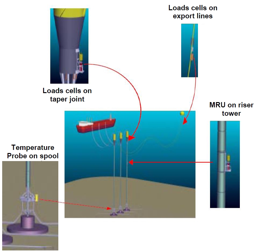
For a riser towers (Girassol hybrid towers) in service conditions, the monitoring system must provide information concerning the system positions, acceleration, loads and flow features (see Figure 12.3, “Typical monitoring system on a hybrid riser system (Girassol field)” ).
Acoustic data transmission devices exist to transmit monitoring results to the FPU without using any further umbilical. All the measurement systems presented below have their own acoustic communication device, or have a data recording system. In addition, in order to avoid the use of a dedicated umbilical, the different monitoring systems should have their own individual power supply unit. Submarine batteries could be used. Such batteries are specially designed for long term applications, and the anodes are replaceable by ROV.
12.3.1 Hybrid riser tower position
It concerns measurements of the bundle and top air can positions (in all directions), such that the hybrid riser excursions can be deduced. The aim is to check that the system excursions stay within the defined excursion envelope, considering the following objectives:
Prevention of clashing with mooring lines
Verification that angle at the bottom connection does not exceed the design value
Assessment of the system eigen values by logging excursions versus time. This will be used to confirm that resonance with the FPU slow drift motions does not occur.
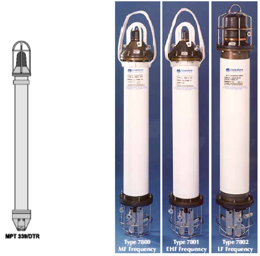
Acoustic transponders is an efficient device to provide accurate position of an hybrid riser. These systems have their own battery, which are retrievable by ROV (battery life: 3months at least). A transponder could be set on top of the air can.
Acoustic transponders are currently used for deep water applications. Some of them are rated up to 7000m. Examples of such systems are presented below:
12.3.2 Accelerations
Linear accelerations and angular velocity of the hybrid system shall be logged at the top Air can and at regular intervals along the bundle. The aim is to determine the amplitude of the short period vibration modes of the system due to VIV.
Quartz accelerometers could be used for their high resolution and accuracy. This is the technology of the VISMU system presented below.
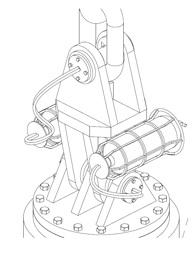
An accelerometer unit can be located at the top air tank. Then, accelerometer units can be fitted regularly along the bundle length, clamped to the central core pipe (as shown in the Figure 12.5, “- VISMU clamped on steel pipe”).
Various accelerometer unit systems exist.
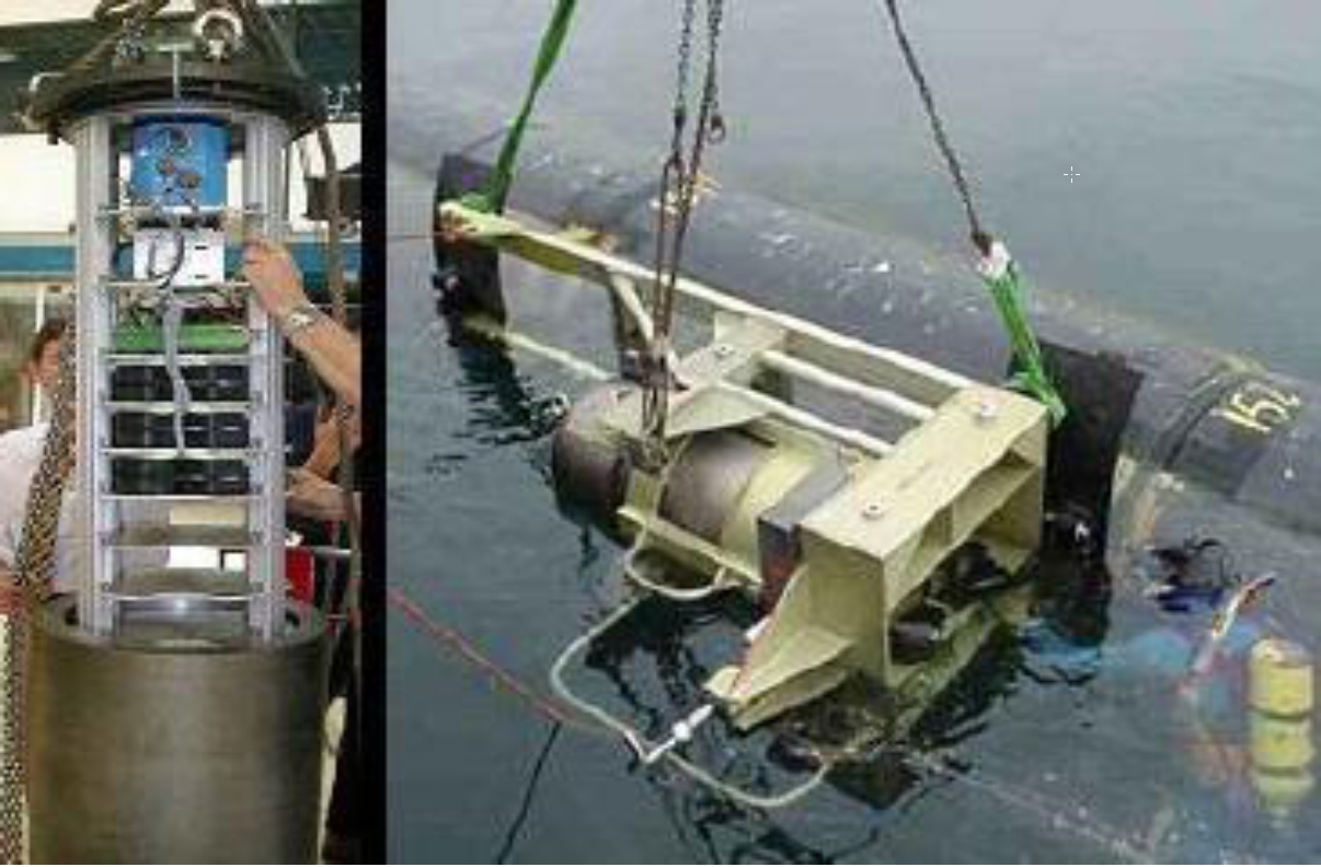
The system VISMU (Vibration and Inclination Subsea Measurement Units) was tested on Petrobras XVIII semi-sub, to assess the condition of the Steel Catenary Riser. This device was designed by Scientific Marine Services, Inc and was rated to 900m water depth. These units are semi autonomous units that can communicate acquired data from the sensors to the FPU via an acoustic link. They also have their own integral batteries.
Motion Recording Units (MRU’s), designed by CYBERNETIX, can be fitted on an hybrid riser and provide bundle dynamic behaviour recording. This device was applied on Total's Girassol field (Angola). The MRU must be located on the foam section at different water depth. These are ROV removable units that can detect displacement magnitude up to 1.5m and angular motions up to 0.5°. Each MRU includes: 3 fiber-optic gyrometers to measure the angles, 1 inertial measurement unit with 3 accelerometers, 1 real-time computer to calculate velocities and displacement. It confirms adequacy of engineering tools in predicting system dynamic behaviour. In addition, this MRU inform on the potential water ingress inside the buoyancy tanks. A significant loss of buoyancy would indeed result in an alteration of the excursion compare to other towers
CorrOcean has designed a concept which is able to record vibrations, movements and inclinations of risers, and is rated to 2500m. It can also quantify the accumulated fatigue damage. Data are available following recorder retrieval by ROV.
12.3.3 Loads exerted on system
It is possible to monitor the loads encountered by the structure at particular and critical points of the system such as the top air can / riser bundle interface, (at the taper joint or the chain tether) and at the bundle bottom section.
The objectives are considered as follows:
To verify that stress in the central core pipe does not exceed the allowable stress
To check that the central core pipe minimum bending radius is not exceeded
To log the stress history and thus to assess fatigue in the central core pipe and to compare remaining structure life time with design predictions.
To determine loads and verify the bottom connector is not over-loaded, and that some parts of the riser system are not flooded.
Note that during a towing operation, an hybrid riser sustains a number of strain cycles due to waves. In order to assess the hybrid riser system remaining fatigue lifetime, encountered stress and deformed shapes can be logged at the following particular points:
Top air can / riser bundle interface,
riser bottom section
Regular locations along the bundle length
During lowering and up-ending operations, it is possible to monitor in real time the stress in the structure (at the critical locations exposed in the previous sections) in order (1) to check that stress does not exceed the specified allowable stress and (2) to check that the specified central core pipe minimum bending radius is not exceeded.
Strain gauges can be used for stress and load monitoring on an hybrid riser. In addition, fibre optic could also monitor stress.
Various stress monitoring systems exist:
Strainstall UK, Ltd has designed a stress-monitoring system, rated to 3000m, which was installed on the Ocean Rig Bingo 9000 semi-submersible drilling unit. The monitored data were channelled topsides via fibre-optic cables.
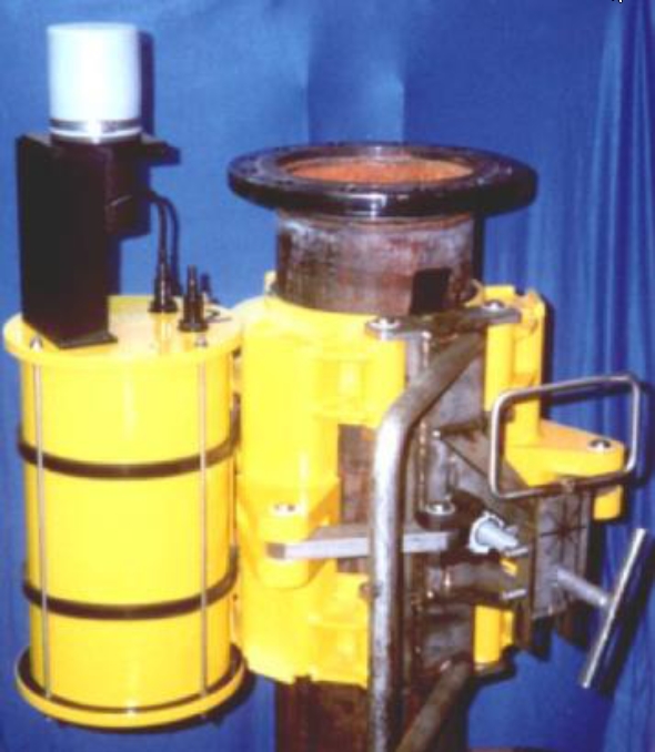
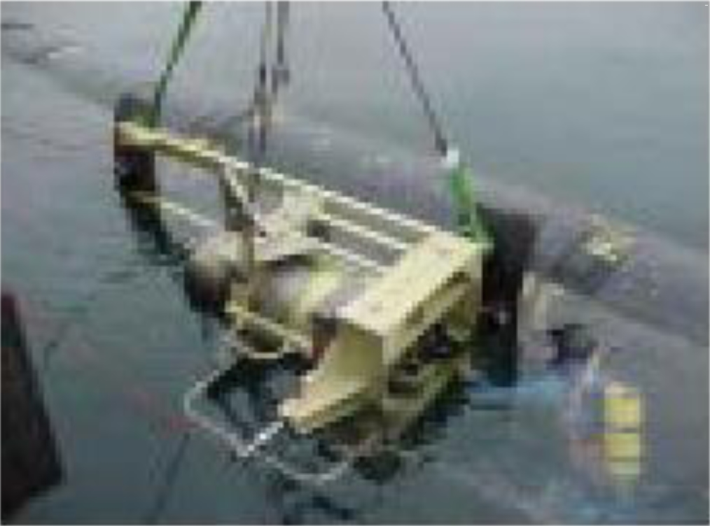
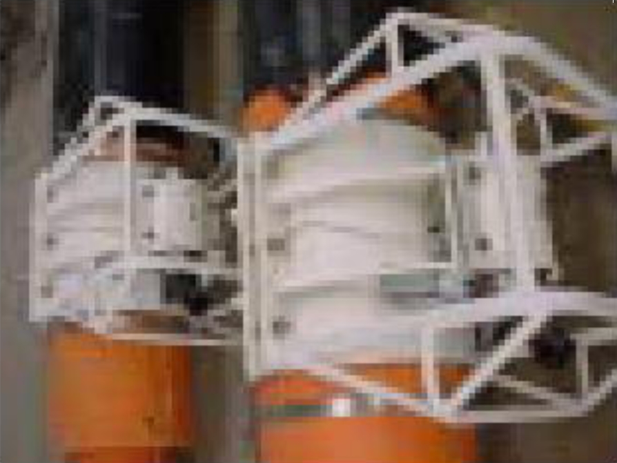
CYBERNETIX performed design of load cells used on the Girassol field in order to monitor stress, tensions and bending moments at critical areas (such as the taper joint). These units can be fitted onto a pipe as shown in the following figure.
The DACOS “flight” Recorder previously presented is also able to measure and record axial and bending strains that can be post processed to determine load and bending moments.
12.3.4 Flow features
For flow assurance purposes, it is possible to monitor the temperature and pressure of the fluids carried in the different production pipes. After data processing performed with an appropriate thermal-hydraulic simulation software, these measurements enable to prevent and detect hydrates apparition.
Two main devices exist to monitor temperature:
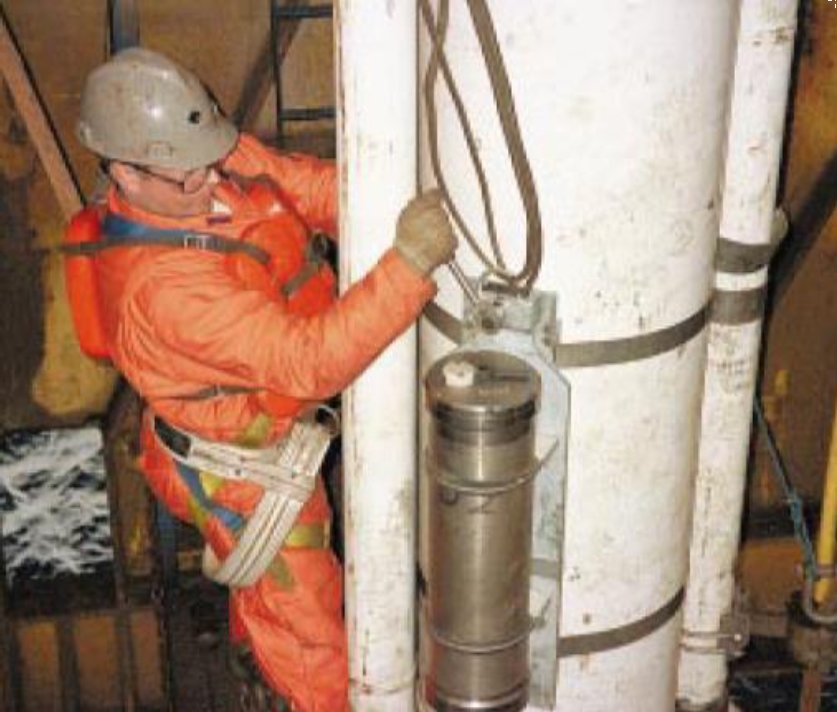
Temperature probes: On the Girassol field, the temperature of the production lines is monitored by temperature probes designed by CYBERNETIX. Temperature sensors are fitted between the pipe and insulation material and recording hardware is located at convenient area’s to allow easy data retrieval. Equipment is designed for data retrieval by ROV and for continuous real time monitoring.
Fibre optic: Two fibre optic principles are to be considered: Raman scattering and Bragg grating system.
- Raman scattering: Temperature is monitored by sending a pulsed laser signal within the optical fibre line. Temperature variation along the fibre induces reflections and signal variations that can be detected and processed by an analyser (opto-electronic device) directly from the fibre end. Temperature readings can be displayed in real-time with a minimum spatial resolution of 2m. The temperature resolution depends on the fibre length; but it is about 1.5 to 2°C (maximum value). The main advantage of this method is that temperature measurements are not affected by other parameters such strain or bending. SENSA Ltd has developed this device for pipeline temperature monitoring.
- Bragg grating system: This technology requires the manufacturing of special types of fibres. The opto-electronic analyzer measures local extension of each sensor which depends on the local thermal expansion of the fibre. Although this solution provides reading of 0.1°C accuracy, the inherent sensitivity of the fibre to axial loads can disturb the measurements. In addition, the risk associated to the system integration and industrialization involving non-standard fibres and micro-mechanical systems requires further investigation. This method is being developed by OPTOPLAN with priority given to stress monitoring.
Two ways are foreseen to install a fibre optic in an hybrid riser system
Fibre optic injection
A pre-installed conduit dedicated to the fibre optic could be fitted in the central core pipe during fabrication. After the system installation, the fibre optic would be installed by injection under pressurised water, with a system patented by SENSA Ltd.
In-place fibres with intermediate connections
During riser tower fabrication, the fibre optic cable would be directly set in place.
12.4 Monitoring of a hybrid 'S' riser
The different monitoring devices described above for a hybrid riser tower are also adapted for an hybrid 'S' riser.
The Control and Integrity Monitoring system of an Hybrid 'S' riser provides information regarding:
The subsea arch position performed using an acoustic navigation system (a Ultra Short Base Line System)
The HySRTM arch position is monitored to check that the HySRTM arch remains within an allowed excursion limit. The maximum excursion is determined based on SCR maximum top and bottom angles, flexible Flowlines and umbilical design, maximum hang-off point loads etc. The HySRTM arch position measurements may be used to assess the system eigenvalues and to confirm that long period resonance with other parts of the system does not occur – e.g. FPU motions.
Two transponders (one operational and one “hot stand-by”) may be installed on the HySRTM arch. The hot stand-by transponder provides redundancy in the system and the means to cross check results. In addition, it allows battery change out to be delayed until a scheduled inspection or maintenance activity.
The subsea arch uplift with 4 stress gauges located in each tether pad-eye.
Strain gauges provide information on tether tensions, allowing uplift of arch to be monitored. A reduction in riser uplift could be the result of leakage of seawater into one or more of the ballast tanks. Differential tensions between bridle pad-eyes could give an indication of which tanks are affected and what means must be taken to resolve the problem – e.g. full or partial evacuation of safety ballast tanks.
Tether tensions could be monitored during riser installation and de-ballasting sequences to check measured values against calculated values and give early warning of any problems with the system during installation.
A sketch of these instrumentation devices is provided on Figure 12.10, “Strain Gauges Sketches used on the Bridle Pad-Eyes”. A sensor in tube shape is got into the rotation axis in which the tension must be measured. The tension is recorded and then transmitted to the platform.
The SCR stress with strain gauges at critical location on SCRS
Strain gauges should be mounted at critical locations on each SCR, e.g. adjacent to the HySRTM arch and touch down zones. Systems are the same as those described in Section Section 12.3.3, “Loads exerted on system”.
The SCR and subsea arch inclination and vibration with accelerometers (see section Section 12.3.2, “Accelerations”).
HySRTM arch and riser inclination and vibration measurements are used to determine the amplitude of short period vibration modes of the system, and to check the SCR catenary shape. Using HySRTM arch vibration measurements together with vibration measurements at various locations on each of the SCRs allows tracking of riser VIV and accumulated riser fatigue.
Other measurements which could be provided if required include process production pressure and temperature in the SCRs. Suppliers include Scientific Marine Services, Cybernetix, Corrocean, 2H and MCS International.


