
11 Installation Techniques
11.1 General
Selection of methods for installing hybrid, flexible or metallic risers is strongly dependent on field development type, vessel capability and availability, and riser material.
The following Table 11.1, “– Installation techniques: Summary table” illustrates the installation techniques that can be considered depending on the type of riser:
Table 11.1 - – Installation techniques: Summary table
TYPE | INSTALLATION TECHNIQUES | VESSEL REQUIREMENTS |
Riser tower | Installation of suction pile Surface or sub surface Tow Method + Upending and flexible jumper connection operations Buoyancy tank towing and installation | 1. Leading Tug 2. Trailing Tug 3. Survey vessel 4. Combined flexible lay and jumper connection vessel |
Single Hybrid Riser | Installation of suction pile J-lay method Buoyancy tank towing and installation | 1. Pipelay vessel equipped with J lay ramp and tensioners, or a dedicated flexible lay vessel 2. Installation vessel equipped with Flex-lay system 3. Multi Service Vessel (survey + ballasting, deballasting, 4. Barge (buoyancy tank transportation) |
Hybrid 'S' Riser | ||
Flexible Riser | Flex-lay with tensioners | 1. Flexible lay vessel (with vertical lay tower) 2. Survey vessel |
1. J lay with tensioners or collar hang off points 2. Reel-lay | 1. Lay vessel 2. Survey vessel | |
1. Leading Tug 2. Trailing Tug 3. Survey vessel |
The installation techniques for flexible and metallic risers are further discussed below.
11.2 Installation of flexible risers
Vessels equipped with dynamic positioning (DP) system, which allows accurate tracking of laying routes, should preferably carry out the installation of flexible Flowlines. The DP system ensures station keeping with selection of optimum heading enables a close approach to floating production systems and eliminates the risks of damage to pipe by anchors in congested areas. In addition, the ideal vessel should have a large pipe and/or cable carrying capacity.
As with any type of offshore installation work it is imperative that the installation vessel and its equipment are suitable for the handling of the flexible product.
In deep waters, the installation of flexible risers required the mobilisation of DP vessel equipped with a Vertical Lay System, which is composed of a vertical derrick, a gutter, an A&R winch, tensioner (s) and hang off/working platform. This equipment is typically located over the moonpool or at the stern of the vessel (i.e. CSO Sunrise 2000) or aside of the vessel (7 Phoenix or 7 mar).
The S systems, Steep S and lazy S, consists of components such as buoyancy tanks, arches and riser bases. The installation vessel will require a crane with sufficient capacity, height and outreach to allow for the over-boarding operations, while controlling the catenary lay radius at the seabed sag-bend. Deck space and payload are also important considerations for both systems.
The Wave systems, Steep, Lazy and Pliant are often used for single well developments or export systems. Utilising less bulky hardware components, wave systems require lighter crane capacity and less deck space than the S systems.
The simplified installation procedures of the different riser configurations are described hereunder:
11.2.1 Flexible riser in “Free hanging” configuration
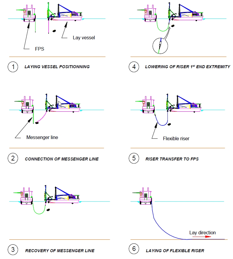
A typical installation procedure would consist of the following phases (see Figure 11.1, “– Main installation phases of flexible riser in free hanging configuration”):
1 – 3. A messenger line is passed from the floating production facility to the installation vessel
4. The upper end of the riser is transferred from the installation vessel to the FPS with the upper section of the riser
5. The upper end of the riser is secured to the riser hang off platform by means of clamp
The flexible riser is paid out from the lay vessel until reaching the touch down point.
Once the touch down point is confirmed by means of ROV, the Flowline is laid in the direction of its final destination
11.2.2 Flexible riser in “Lazy S” configuration
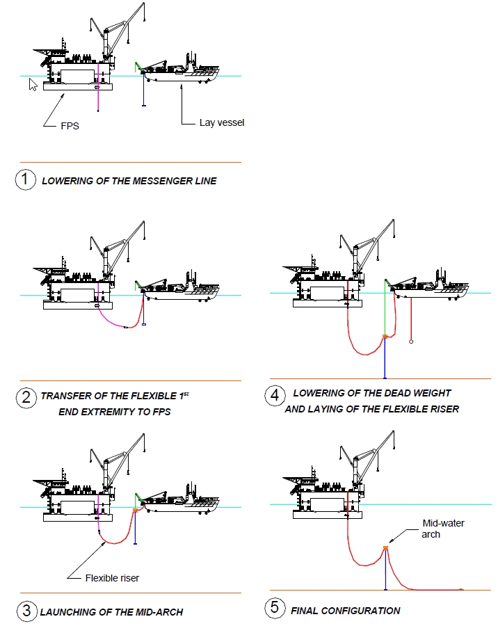
A typical installation procedure would consist of the following phases (see Figure 11.2, “Main installation phases of flexible riser in Lazy S configuration”):
1. A messenger line is passed from the floating production facility to the installation vessel
The upper end of the riser is transferred from the installation vessel to the FPS with the upper section of the riser
3. The mid-water arch is launched and positioned at mid-depth by means of the dead weight while paying out of the riser continues
4. The retaining swivel is disconnected from the mid-water arch and the lower end of the riser is laid on the sea bed
5. The Flowline is laid in the direction of its final destination
11.2.3 Flexible riser in “Lazy Wave” configuration
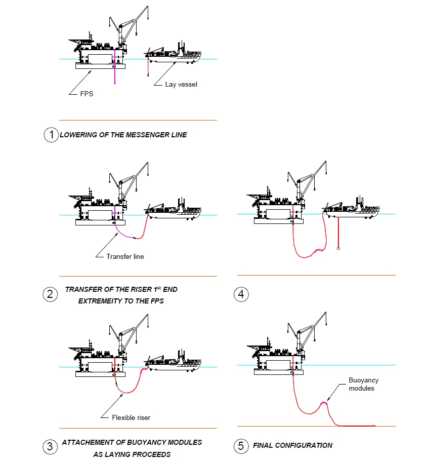
A typical installation procedure would consist of the following phases (see Figure 11.3, “Main installation phases of flexible riser in Lazy Wave configuration”):
A messenger line is passed from the floating production facility to the installation vessel
The upper end of the riser is transferred with the upper section of the riser
The buoyancy modules are attached to the riser as laying proceeds and launched
The installation of the riser continues by the paying out of the Riser
The Flowline is laid in the direction of its final destination
![[Tip]](tip.png) | Tip Click these links below for access to 3D resources: |
11.2.4 Flexible riser in “Steep S” configuration
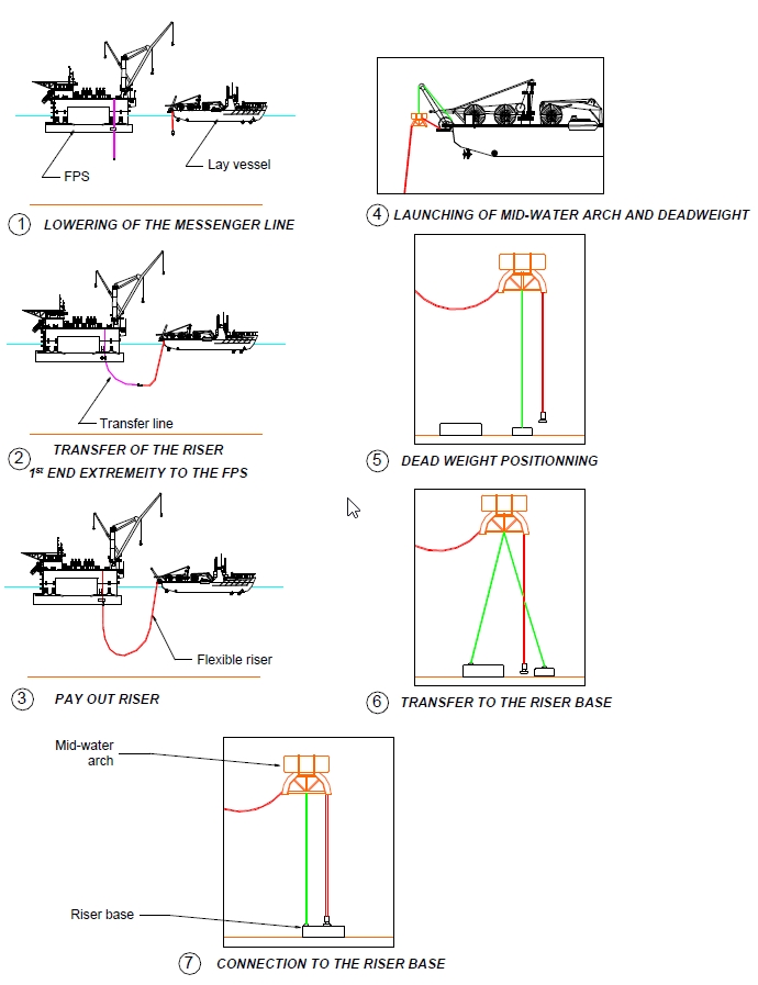
A typical installation procedure would consist of the following phases (see Figure 11.4, “Main installation phases of flexible riser in Steep S configuration”):
A messenger line is passed from the floating production system to the installation vessel
The upper end of the riser is transferred with the upper section of the riser
The upper end of the riser is connected to the floating production system while paying out of the riser continues
The mid-water arch and the dead weight are launched
The dead weight is positioned at a predetermined location. The riser may be abandoned at this stage for further connection
The lower end connection is positioned relative to the riser base by means of a come-along (or pulling line)
The lower end connection is tied-in to the riser base
11.2.5 Flexible riser in “Steep Wave” configuration
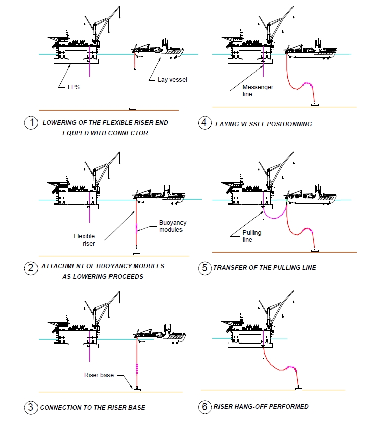
A typical installation procedure would consist of the following phases (see Figure 11.5, “Main installation phases of flexible riser in Steep Wave configuration”):
Lowering of the flexible riser and its automatic connector (vertical entry) at the stern of the installation vessel.
Installation of the buoyancy modules at adequate locations on the flexible riser.
The flexible riser and its automatic connector is directed towards the riser base by means of ROV.
Perform automatic connection of the flexible riser onto the riser base by means of ROV.
Paying out of the remaining part of the flexible riser and the vessel takes its position for the transfer of flexible riser to the floater.
On completion of messenger and pulling lines recovery, connect the pulling line to the pulling head mounted on the flexible riser and start the transfer ot the flexible riser to the floater.
Once load transfer is completed, recover A&R cable, resume pulling the flexible riser and secure it to the hang off platform.
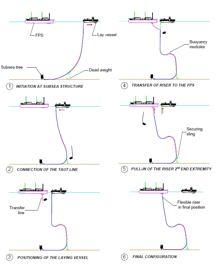
11.2.6 Flexible riser in “Pliant Wave” configuration
A typical installation procedure would consist of the following phases (see Figure 11.6, “Main installation phases of flexible riser in Pliant Wave”):
The first end of the Flowline is initiated at the subsea structure and the Flowline is laid in the direction of the dead weight.
Installation of the clamp/attachment line sub assembly and the buoyancy modules at adequate locations on the flexible line
Perform the connection of the attachment line to the dead weight by ROV
Recover flexible line to surface to form the loop before resume paying out flexible in the direction of the floater
A messenger line is passed from the floating production system to the installation vessel for the transfer of the pull in cable.
Once the pull in cable is connected to the pull in head mounted on top of the riser, the second end of the riser is lowered with the A&R cable.
On completion of the load transfer and disconnection of the A&R cable by ROV, the second end of the riser is pulled in I or J tube then secured to the hang off platform.
11.3 Installation of steel risers
11.3.1 General
Outwith the conventional drilling riser running techniques used for the deployment of top tensioned riser from semi-submersible, TLP and Spar, the two most promising installation techniques for metallic risers are J-lay, Reel-lay and towing (not so many SCR installed by towing). The Reel-lay method involving plastic deformation of welds and pipes may affect fatigue life of metallic risers. The installation techniques for metallic risers are described hereafter:
The installation techniques for metallic risers are described hereafter:
11.3.2 J lay technique
The main advantages of J-lay technique are:
Increased water depth capability as J-lay is high lay capacity method (up to 1500 mT)
Reduced weather sensitivity
Reduced pipe stresses and lower tension due to steeper pipe departure
Easier start-up, termination and abandonment & recovery operations
Reduced complexity attaching buoyancy and ballast during lay
Lower horizontal thrust requirement (compared to S-Lay) allowing the use of DP vessel
No damage to insulation coating (no contact between the coating and a reel or rollers)
During J-lay, pre-welded pipe strings consisting of 1 to 6 pipe joints (each approx. 12m long) are welded to the riser, which is clamped on an inclined lay ramp. Pipe joints are welded together, NDT tested and coated before leaving the working platform at a defined angle.
The simplified installation procedure of a steel catenary riser with second end transferred to the floater is illustrated in Figure 11.7, “Main installation phases in steel catenary riser”:
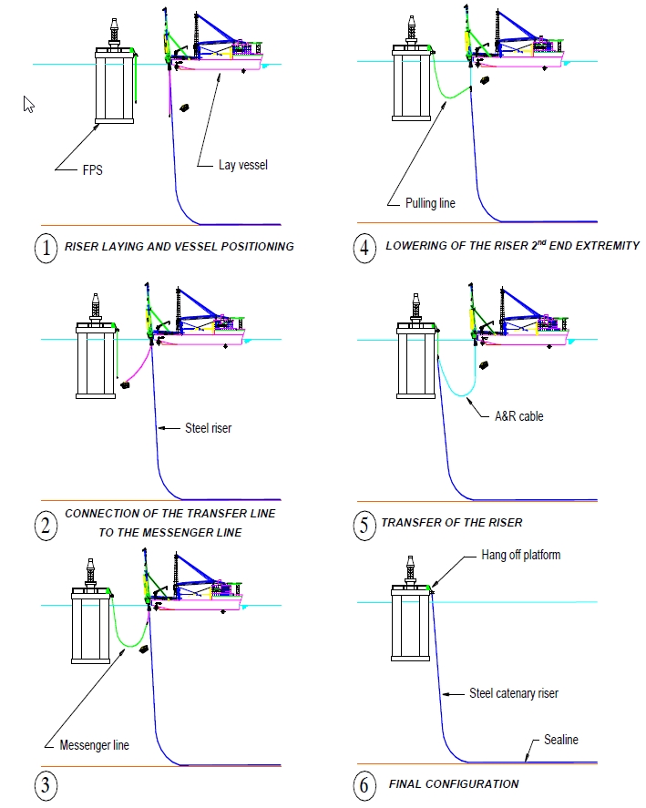
A typical installation procedure would consist of the following phases:
When the pipelay vessel is about 130m away from the floating production platform, a messenger line is lowered from the floating production system.
A transfer line is lowered from the pipelay vessel at the same water depth to allow ROV to connect the transfer line to the messenger line.
When the messenger line reaches the working platform of the pipelay vessel, it is connected to the pulling head on top of the flexjoint welded to the steel riser.
The steel riser is lowered below the vessel on the pipelay's abandonment and recovery cable until the riser starts swinging over towards the floating production system
After disconnection of A&R cable by means of ROV release hydro-acoustic shackle, a pull-in, run from hydraulic winch on the platform, is used to finally pull the riser into the receptacle.
The pipeline is then free flooded, the spool piece that connects the riser to preinstalled hull piping is installed and the pipeline system is ready for final testing.
11.3.3 Tow out method
Tow out is an alternative method of installing metallic risers. This necessitates onshore fabrication of the riser, followed by surface, sub-surface or near-seabed tow to the offshore site. The tow out has the advantage that the riser can be inspected and tested before it is towed out. This technique is followed by an upending operation and a connection of the riser at the foundation.
This technique has been used for the Girassol riser tower (see Section 11.4.1, “Hybrid riser tower installation”).
11.3.4 Drilling riser running techniques applied to top tensioned risers
The main technique used for the installation of top tensioned risers is the conventional drilling riser running techniques as used for the TLP (see )
The following will describe two different riser installations, but also based on drilling riser technique: (1) top tensioned riser tower deployment from a semi-submersible (Enserch Copper Project, Garden Bank 388) and a SPAR (Oryx Neptune Project).
Installation of top tensioned riser tower from semi-submersible
Recover the protective cover over the riser base with the drill pipe running tool
The assembly composed of lower riser connector and stress joint is brought up through the V door and lowered down through the spider setting the upper end of the stress joint on the spider
Bring the first riser joint up into the derrick, land it on the upper stress joint flange and perform bolt flange connection
Perform regular riser joint (e.g. 12m long) installation to reach the required riser length
Install quarter sections of external air tank on the last 2 riser joints (or required length) by bolting them together around the riser joint as it run through the moonpool
Bolt the upper riser connection mandrel to the top of the last riser joint to complete the assembly of rigid part of the Riser
Install the riser installation string on the upper riser connection mandrel then lower the riser to the riser base using the heave and motion compensator
Once the lower riser connector is landed on the riser base and confirmed by ROV, the connector is hydraulically locked by ROV.
Pump air in the two external air tanks through a temporary umbilical to make the riser neutrally buoyant
Lower gas export line bottom termination through the running string by welding joints as needed, land and lock both ends from the inside using drill pipe running tool
Using guide frame and assisted by diver or ROV, position casing and tubing into the proper location within the upper riser connection package
Lower annulus and production lines having stab latches at the lower end that lock to riser base receptacles
Pump air in the two external air tanks to make the riser positively buoyant and therefore self-supporting
Position the upper riser connector package in the moonpool and connect the flexible lines to the gooseneck hubs at one end and pontoon porches at the other
Using drill pipe, lower the upper riser connector package to the upper riser connector mandrel
With the lift off cylinders, lower the mini-connectors onto the Flowline hubs and hydraulically lock them in place.
Lower and connect the upper riser sheave package to the upper riser connector package
Activate the riser management system to maintain the riser within the desired watch circle
Installation of top tensioned riser from SPAR (see Figure 5.17, “Top tensioned riser applied to SPAR” and Figure 5.19, “– Detailed description of Neptune SPAR production riser”)
![[Note]](note.png) | Note Buoyancy tanks and stems are installed when the deck module is installed. The lower two of each set of three tanks are flooded and the tanks are resting on their down stops. This placed the upper end of the buoyancy tank's stem at the production deck level where the riser-landing ring with the load cells is attached. |
riser installation starts with the crane lifting the tieback connector/stress joint/lower transition joint and keel joint subassemblies aboard, upending and hanging each in a vacant well slot.
The rig is skidded over the keel joint first, which is picked up through the rotary table and stored to one side. Then the rig is skidded over the tieback connector/stress joint/lower transition joint, which is also picked up through the rotary table
Once the rig is skidded over the well slot and the messenger line, attached to the lower end of the tieback connector stab sub, the subassembly is landed in the spider
Buoyant joints are lifted up through the V-door and made up to the threaded-and-coupled connection at the upper end of the lower transition joint. Threaded-and-coupled riser joints are added until the proper length is reached for keel joint placement.
An upper transition joint, the keel joint, and second upper transition joint are placed in the string before running of standard joints continues.
When total riser length is reached, the waveform joint is made up and the string slowly lowered as the ROV observes and laterally assists in stabbing the tieback connector into the wellhead. The ROV then locks the connector through an hydraulic hot stab. Afterwards, riser string over-pull and internal pressure tests are made to verify connection integrity.
The riser is pulled to its operating tension while the SPAR is de-ballasted to its proper draft. The adjustable riser support structure is extruded to its full up position, the waveform joint slips set, and the surface wellhead is attached to the landing ring. With the riser lowered slightly, the excess length of waveform joint is removed and the isolation seal and tubing spool are installed. Once the BOP spool and surface BOP are attached, the well is ready for downhole completion activities.
After the downhole completion is installed and the production and gas lift tubing is landed and hung from a packer just below the seafloor wellhead, dual tubing strings along with a control/chemical injection umbilical are run through the riser and suspended from the surface wellhead. Finally the surface tree is landed and locked to the tubing spool and the jumper Flowlines and umbilical connect the platform based manifolds and control equipment.
When the well is on stream, the riser's weight is transferred to the buoyancy tanks. This load transfer requires careful co-ordination of buoyancy tank deballasting and Spar ballasting. Once the load transfer is complete, the adjustable riser support structure is removed and the riser system tanks provide complete support and tensioning of the production riser system.
11.4 Installation of hybrid riser systems
| Tip Click these links below for access to 3D resources: |
11.4.1 Hybrid riser tower installation
One of the advantages of a hybrid riser tower is to enable different installation activities such as heavy lift, rigid line construction, flexible deployment, structure pulling and subsea work activities whilst utilising the same installation vessel.
Different installation procedures can be used depending on the riser tower to be installed. Here riser tower with integrated buoyancy tank like for Girassol Riser Towers (North, Center and South) has been considered.
I. riser Fabrication
The Fabrication of the Hybrid riser Tower is performed onshore in a dedicated construction yard.
The assembly construction yard shall be selected to allow an esay launching of the riser tower, i.e. to have an access to sheltered water.
The riser Tower fabrication will cover :
The construction of the riser bundle
The construction of the riser foundation,
The construction, and the connection of the buoyancy tank,
The hydrotest of all the pipelines
I. riser Tow / Upending procedure
This procedure has been used for Girassol project. The installation of the multi-line hybrid riser tower was subdivided into five phases:
The foundation installation
The tow out from the onshore fabrication site where the riser tower is assembled and tested.
The upending operation
The connection of the tower to the riser base
Flexible jumpers installation
Tow-out operation
The tow out operation consists in bringing the tower on site by towing it with the help of leading and trailing tug (assisted by a survey vessel). The tower is supported by means of subsurface and surface buoys, while its own weight is adjusted by temporary flooding of some Flowlines.
The buoyancy tank may be submerged to a depth of about -50m from surface by deploying the ballast chain from the trailing tug. This operation may be required to reduce the stress generated by waves at the taper joint level between the buoyancy tank and the bundle.
The depth was monitored using transponders and the motions are recorded, notably for damage assessment.
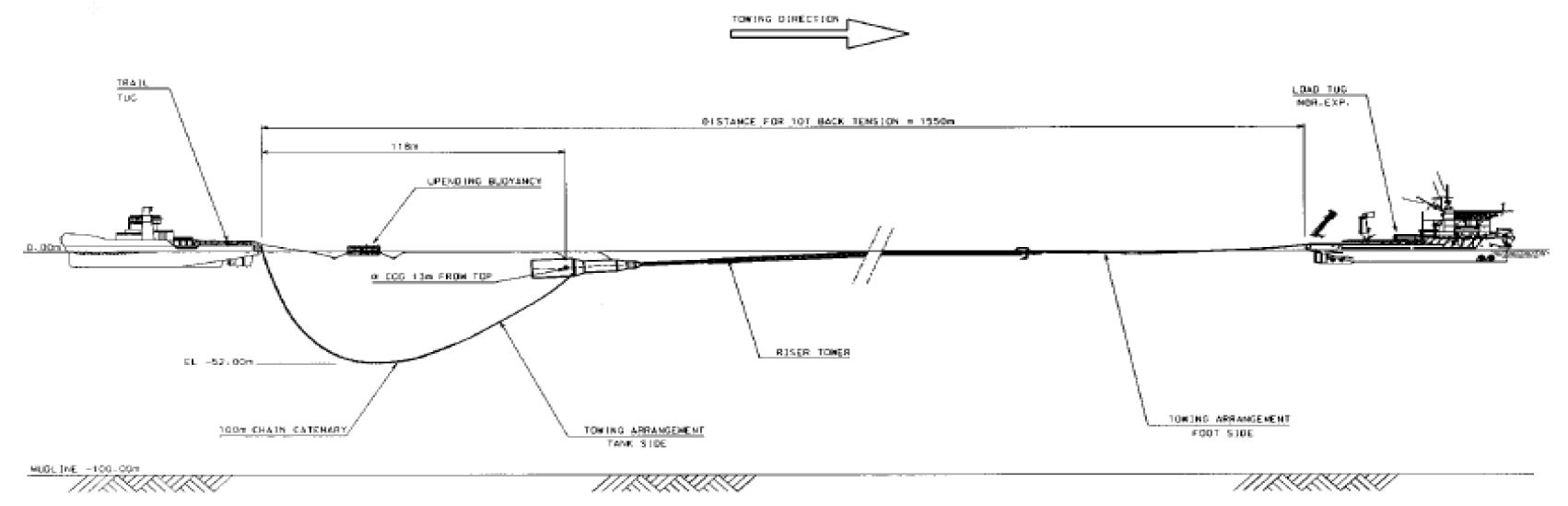
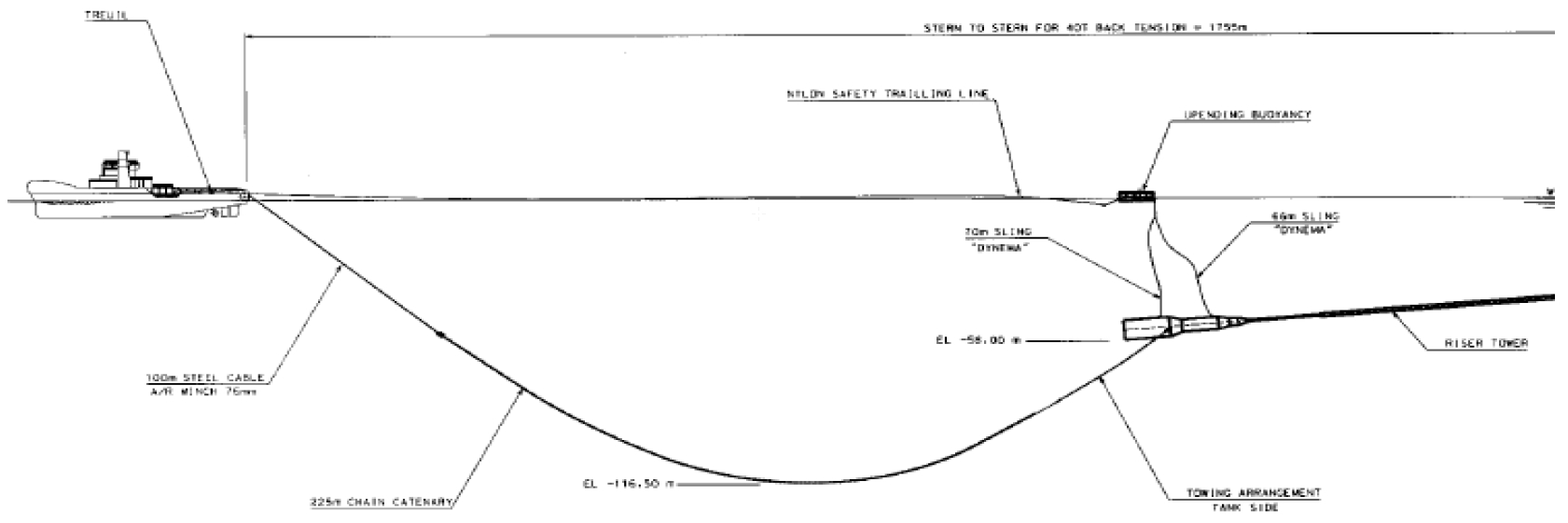
Up-ending operation
Once on site, the up-ending operation is performed. The tugs apply the adequate tension to prevent any excessive bending while the deployment of an anchor from the towing vessel is performed. Alternatively , a free fall up-ending method can be followed.
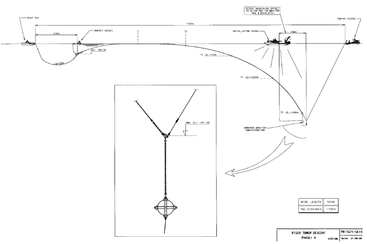
Monitoring of tension and curvature of the riser tower is performed continuously during the operation by the survey vessel using acoustic transponders installed on the riser tower.
The back tension is maintained by the rear tug.
The descent is carried out under ROV Monitoring.
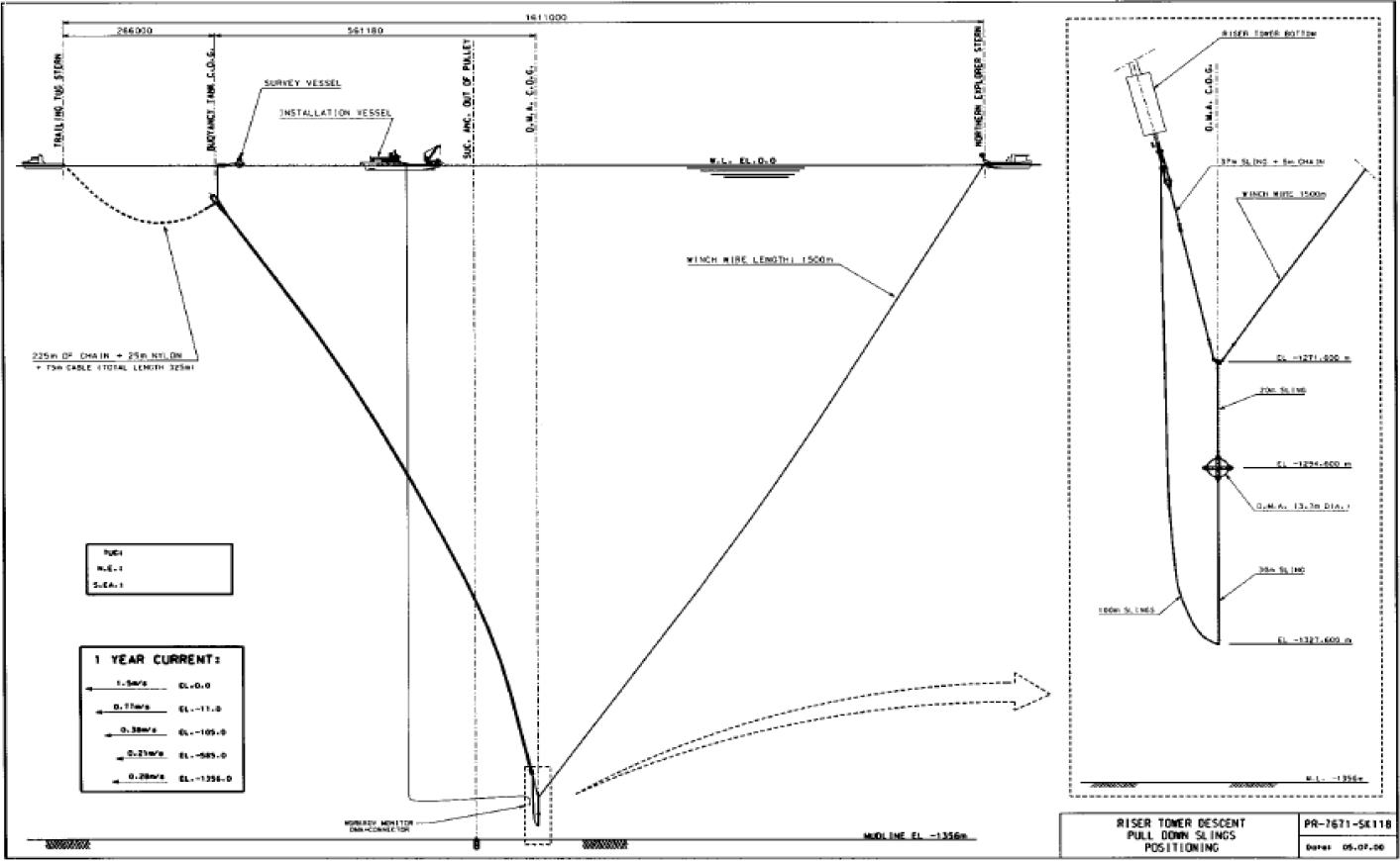
On completion of the up-ending operation, the riser tower is positionned vertically above the riser base (suction anchor).
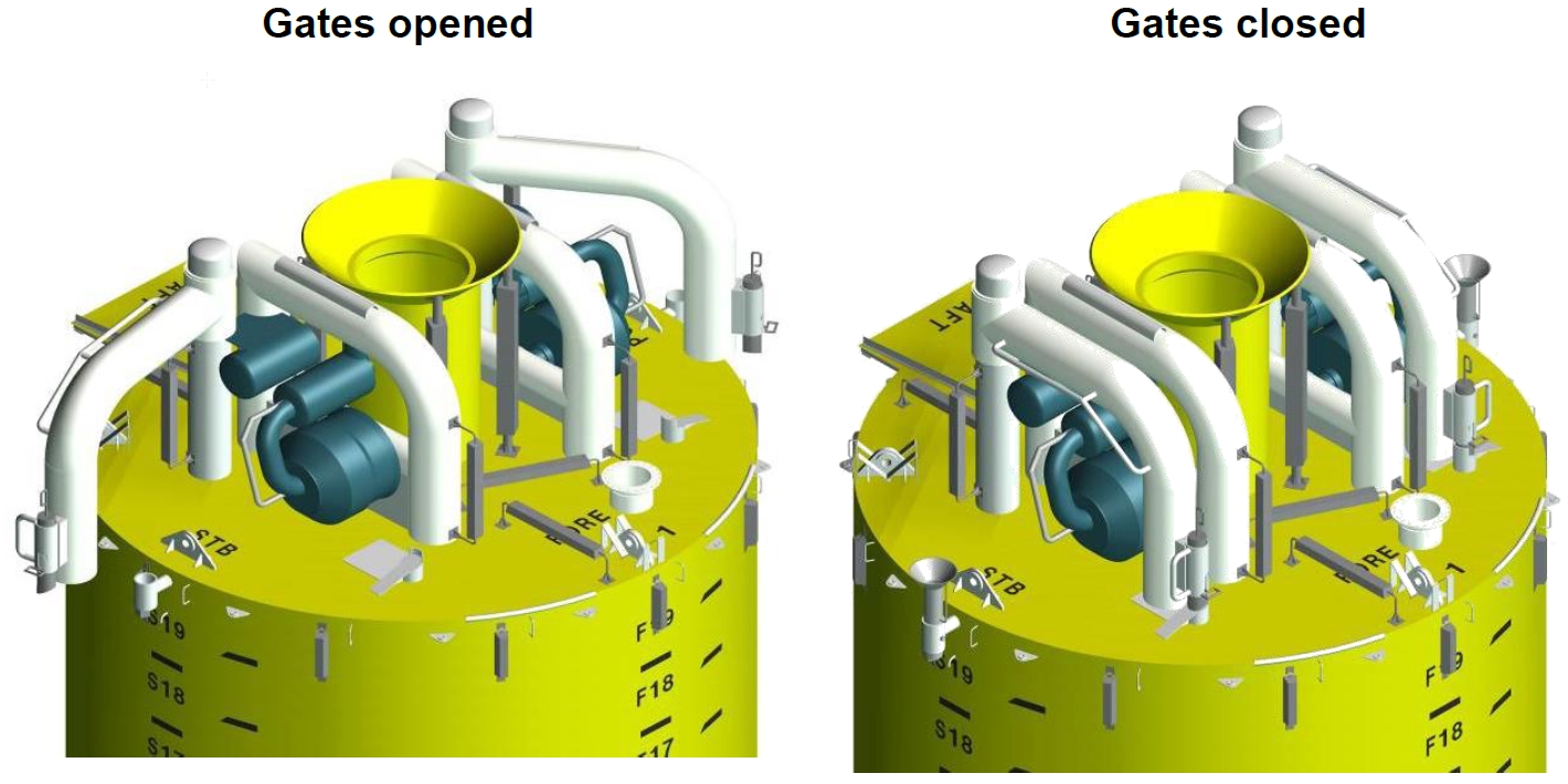
The pull-down sling is inserted the returm sheaves, and the suction anchor gates are closed.
Connection operation
The rear tug moves towards the lead tug, to continue the vertical alignment.
The connection of the riser tower to the riser base is performed by ballasting , and by combination of lead tug motions and winch operation.
The bottom end of the riser is pulled inside the receptacle.
Once the tieback connector is landed on the riser base and confirmed by ROV, the connector is hydraulically locked.
The tank is de-ballasted to bring the bottom tension to around 350 te.
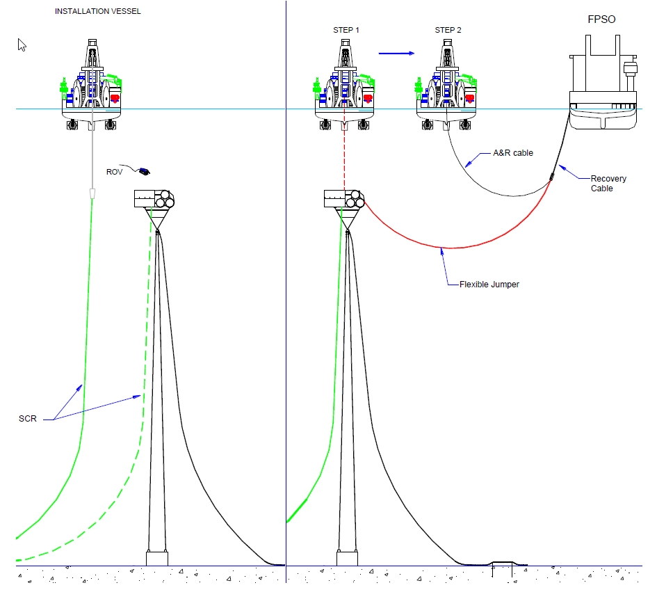
Flexible jumpers installation
The flexible risers are pre-installed along the tower and connected at a later phase, after the FPSO has arrived on site.
A typical top connection mainly consists in:
Disconnect first end flexible riser from the riser tower
Once the disconnection is completed, the flexible riser is laid in the direction of the FPSO
When the load is transferred to the floating production platform, the flexible jumper is pulled in an I tube
Lock the flexible riser bend stiffener in the Itube and secured the flexible riser to the hang off platform.
II. SHR installation
One alternative of a single line riser tower installation used on Kizomba A and B is composed by six phases:
riser Tower foundation Installation
Fabrication and J-Lay deployment of the tower
Flexible Jumper Installation
Up-ending of the buoyancy tank
riser tower lowering
Connection of the riser string
Fabrication and J-Lay deployment
The top and bottom assemblies are loaded on board the construction vessel already prefabricated. The riser line pipes are delivered in single joint and welded in quad joint on the firing line, as in standard pipe laying production. Then the quad-joints are welded and deployed through the J-lay tower until the required length is achieved. The full assembly is transferred from the J-lay tower to a hang-off platform.
Flexible Jumper Installation
The flexible jumper is partially over-boarding and connected to the top assembly of the riser tower located on the hang-off platform. The pigging loop between flexible and riser pipe is connected as well as the chain to the top assembly. Then the flexible jumper is completely over-boarded and stored along the rigid pipe string.
Up-ending of the buoyancy tank
The buoyancy tank is lifted from the cargo barge on a dedicated upending system. The buoyancy tank bottom flange is bolted to the tether top flange.
Riser tower lowering
Once the elements are all assembled together (from riser base assembly to the buoyancy tank), the assembly is lifted and over-boarded in water. Then the system is lowered in steps in order to allow free flooding of the buoyancy tank and to bring the bottom assembly just above seabed.
Connection of the riser string
The riser tower is brought above the foundation. The ROV connects the hold back slings to the tower bottom assembly pull-in device, to secure the whole riser and buoyancy tank to the foundation before commencing of dewatering operation. Then the buoyancy tank is de-watered, with nitrogen, until being slightly buoyant.
When the riser tower is buoyant, the A&R wire is released and the SHR stays in position retained
on the holdback slings connected to the foundation.
The riser is pulled down into the riser base joint receptacle and locked in position, by pulling from the vessel through the pulling system located on the foundation. Then, the buoyancy tank is completely dewatered up to operational condition to allow enough tension in the riser.
Once the floating vessel is installed, the flexible end is recovered to surface and connected to its I-tube.
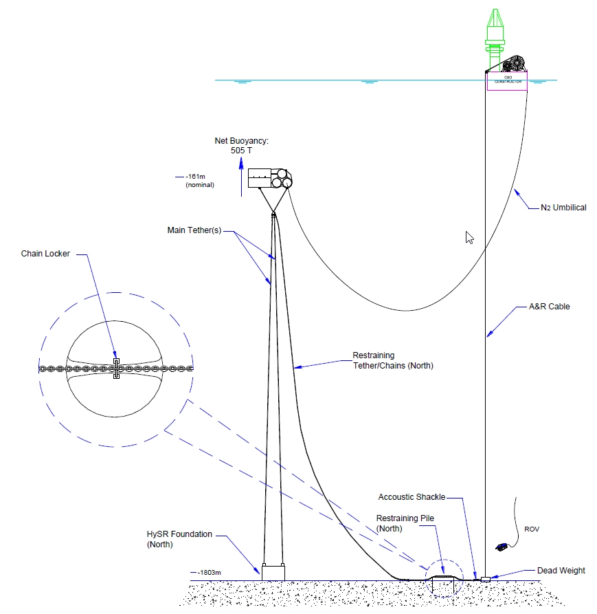
11.4.2 Hybrid 'S' riser Installation
The proposed logical installation sequence for the completed HySRTM system with dual tether (e.g. foundation, arch, tethers, risers, etc) is as follows:
HySRTM foundations Installation: two main foundations and two piles for the restraining tethers. These foundations require precise installation accuracy (+/- 1.5m and +/-5°) and should be installed relative to the FPU mooring system using LBL hydro acoustic positioning. Pulling test must be completed.
Subsea buoy towing: following a sufficient soil curing period (e.g. 1 to 2 months), the HySRTM subsea arch is towed to site. The buoyancy of the buoy having been adjusted to have only about 90T bet buoyancy.
First main tethers installation: the first main tethers are connected to the bridle frame located under the buoy
Second main tethers and restraining tethers installation : these lines are connected to the buoy and a part is paid out under the buoy.
Subsurface buoy lowering: a dead weight is installed on the buoy to make the buoy progressively dive. Compartments are N2 pressurized during the lowering.
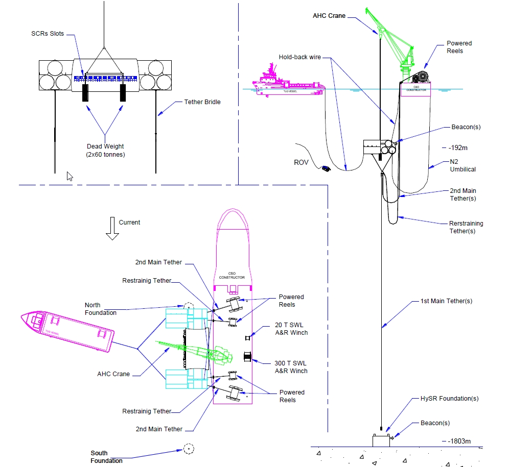
Main tethers connections: Once the buoy is low enough, the first set of main tethers are connected. Then the second set of main tethers is installed and some buoy compartments are deballasted. The dead weight is recovered.
Polyester tethers stretch removal: in case of polyester main tether, a stretch removal sequence has to be done by deballasting and reballasting a large quantity of compartments.
Restraining tether lowering and connecting
Flexible jumper installation: once the SCR is at lay ramp hang-off, the flexible jumper end-fitting is connected to the SCR. Flexible risers are then be laid over the subsea arch-tray and subsequently cross-over to the FPU hang-off, or hung freely from the arch.
Next risers installation: subsea arch buoyancy is re-adjusted for next riser installation. This is repeated for all Flowline/riser installation (including umbilicals installation).
Pre-commissioning: once each riser or umbilical is hung-off at the FPU, or hung on the arch its pre-commissioning activities can commence.


